www.proform.com Model No. PFTL59512.0 Serial No. Write the serial number in the space above for reference. Serial Number Decal QUESTIONS? If you have questions, or if parts are damaged or missing, DO NOT CONTACT THE STORE; please contact Customer Care. IMPORTANT: Please register this product (see the limited warranty on the back cover of this manual) before contacting Customer Care. CALL TOLL-FREE: 1-888-533-1333 Mon.–Fri. 6 a.m.–6 p.m. MT Sat. 8 a.m.–4 p.m. MT ON THE WEB: www.proformservice.
TABLE OF CONTENTS WARNING DECAL PLACEMENT . . . . . . . . . . . . . . . . . . . . . . . . . . . . . . . . . . . . . . . . . . . . . . . . . . . . . . . . . . . . . . .2 IMPORTANT PRECAUTIONS. . . . . . . . . . . . . . . . . . . . . . . . . . . . . . . . . . . . . . . . . . . . . . . . . . . . . . . . . . . . . . . . . . 3 BEFORE YOU BEGIN. . . . . . . . . . . . . . . . . . . . . . . . . . . . . . . . . . . . . . . . . . . . . . . . . . . . . . . . . . . . . . . . . . . . . . . .5 PART IDENTIFICATION CHART.
IMPORTANT PRECAUTIONS WARNING: To reduce the risk of burns, fire, electric shock, or injury to persons, read all important precautions and instructions in this manual and all warnings on your treadmill before using your treadmill. ICON assumes no responsibility for personal injury or property damage sustained by or through the use of this product. 1. It is the responsibility of the owner to ensure that all users of this treadmill are adequately informed of all warnings and precautions. 12.
20. The heart rate monitor is not a medical device. Various factors, including the user’s movement, may affect the accuracy of heart rate readings. The heart rate monitor is intended only as an exercise aid in determining heart rate trends in general. 24. Do not change the incline of the treadmill by placing objects under the treadmill. 25. Never insert any object into any opening on the treadmill. 26. Inspect and properly tighten all parts of the treadmill regularly. 21.
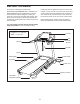
BEFORE YOU BEGIN Thank you for selecting the revolutionary PROFORM® PERFORMANCE 400 C treadmill. The PERFORMANCE 400 C treadmill offers an impressive selection of features designed to make your workouts at home more enjoyable and effective. And when you’re not exercising, the unique treadmill can be folded up, requiring less than half the floor space of other treadmills. reading this manual, please see the front cover of this manual.
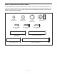
PART IDENTIFICATION CHART Use the drawings below to identify small parts used for assembly. The number in parentheses below each drawing is the key number of the part, from the PART LIST near the end of this manual. The number following the key number is the quantity used for assembly. Note: If a part is not in the hardware kit, check to see if it is preattached. Extra parts may be included.
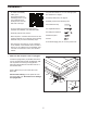
ASSEMBLY • To watch an assembly video, go to http://productvideo.co/ assembly/proform or use your mobile phone or smartphone to read the QR code at the right. • Left parts are marked “L” or “Left” and right parts are marked “R” or “Right.” • To identify small parts, see page 6. • Assembly requires the following tools: the included hex key • To hire an authorized service technician to assemble the treadmill, call 1-800-445-2480.
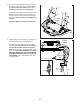
2. Identify the Left Upright (75). Have a second person hold the Left Upright near the Base (80). 2 75 See the inset drawing. Tie the wire tie in the Left Upright (75) securely around the end of the Upright Wire (70). Then, insert the Upright Wire into the lower end of the Left Upright as you pull the other end of the wire tie through the Left Upright. Wire Tie 70 Wire Tie 70 75 80 3. With the help of a second person, hold the Left Upright (75) against the Base (80).
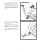
4. Identify the Left and Right Base Covers (73, 74). Slide the Left and Right Base Covers onto the Left and Right Uprights (75, 76) as shown. 4 76 75 74 73 5. Set a Handrail (71) onto the Left Upright (75). Make sure that the Upright Wire (70) is not pinched. 5 Attach the Handrail (71) with two 5/16" x 2 1/4" Screws (7) and two 5/16" Star Washers (8). Start both Screws before tightening them. 7 8 Attach the other Handrail (not shown) in the same way. Note: There is no wire on the left side.
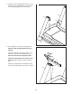
6. Set the console assembly face down on a soft surface to avoid scratching the console assembly. Remove and save the four 1/4" x 1/2" Screws (9). They will be used in step 8. 6 10 10 Identify the Left Tray (90) with the writing on the bottom. Attach the Left Tray with four #8 x 1/2" Screws (10). Start all four Screws before tightening them. Be careful not to overtighten the Screws. 10 90 9 Attach the Right Tray (85) in the same way. 10 Console Assembly 85 9 7.
8. Set the console assembly on the Handrails (71). Be careful not to pinch any wires. Insert the excess Upright Wire (70) into the Left Upright (75). 8 Attach the console assembly with the four 1/4" x 1/2" Screws (9) removed in step 6 and four 1/4" Star Washers (11). Start all four Screws, and then tighten them. 71 71 70 11 11 9 9. I MPORTANT: To avoid damaging the Pulse Crossbar (31), do not use power tools and do not overtighten the #10 x 3/4" Screws (13).
10. Identify the Left and Right Handrail Inserts (35, 69). 10 Attach the Left Handrail Insert (35) to the left Handrail (71) with three #8 x 3/4" Screws (6). Note: Slide the Left Handrail Insert up against the console assembly before tightening the Screws. Console Assembly 35 Attach the Right Handrail Insert (69) in the same way. 71 69 6 71 6 11. Identify the Left and Right Handrail Covers (72, 88).
12. Raise the Frame (49) to the position shown. Have a second person hold the Frame until this step is completed. 12 Orient the Storage Latch (51) so that the large barrel and the latch knob are oriented as shown. 49 Attach the lower end of the Storage Latch (51) to the Base (80) with a 3/8" x 2" Bolt (12) and a 3/8" Nut (3). 3 12 Attach the upper end of the Storage Latch (51) to the Frame (49) with a 3/8" x 2" Bolt (12) and a 3/8" Nut (3). Latch Knob 51 Large Barrel 3 12 80 13.
OPERATION AND ADJUSTMENT HOW TO CONNECT THE POWER CORD nominal 120-volt circuit capable of carrying 15 or more amps. To avoid overloading the circuit, do not plug other electrical devices, except for lowpower devices such as cell phone chargers, into the surge suppressor or into an outlet on the same circuit. IMPORTANT: The treadmill is not compatible with GFCI-equipped outlets and may not be compatible with AFCI-equipped outlets.
CONSOLE DIAGRAM FEATURES OF THE CONSOLE You can even listen to your favorite workout music or audio books with the console’s stereo sound system while you exercise. The treadmill console offers an impressive array of features designed to make your workouts more effective and enjoyable. When you use the manual mode, you can change the speed and incline of the treadmill with the touch of a button. As you exercise, the console will display instant exercise feedback.
HOW TO TURN ON THE POWER HOW TO USE THE MANUAL MODE IMPORTANT: If the treadmill has been exposed to cold temperatures, allow it to warm to room temperature before you turn on the power. If you do not do this, you may damage the console displays or other electrical components. 1. Insert the key into the console. Plug in the power cord (see page 14). Next, locate the power switch on the treadmill frame near the power cord. Press the power switch into the reset position.
5. Follow your progress with the displays. 6. Measure your heart rate if desired. The matrix—When you select the manual mode, the matrix will display a track that represents 1/4 mile (400 m). As you exercise, the indicators around the track will appear in succession until the entire track appears. The track will then disappear and the indicators will again begin to appear in succession.
HOW TO USE AN ONBOARD WORKOUT The workout will continue in this way until the last segment of the profile flashes in the display and the last segment ends. The walking belt will then slow to a stop. 1. Insert the key into the console. See HOW TO TURN ON THE POWER on page 16. Note: The calorie goal is an estimate of the number of calories that you will burn during the workout. The actual number of calories that you burn will depend on various factors such as your weight.
HOW TO USE AN IFIT WORKOUT When you select an iFit workout, the display will show the name, duration, maximum speed setting, and distance of the workout. The display will also show the approximate number of calories you will burn during the workout and a profile of the speed settings of the workout. Note: To use an iFit workout, you must have an optional iFit module. To purchase an iFit module at any time, go to www.iFit.com or call the telephone number on the front cover of this manual.
HOW TO USE THE STEREO SOUND SYSTEM Next, press the play button on your iPod, MP3 player, Increase CD player, or other personal Decrease audio player. Adjust the volume on your personal audio player or press the volume increase and decrease buttons on the console. To play music or audio books through the console’s stereo speakers, you must connect your iPod, MP3 player, CD player, or other personal audio player to the console through the audio jack.
THE INFORMATION MODE CONTRAST LVL—Press the Incline increase and decrease buttons to adjust the contrast level of the displays. The console features an information mode that keeps track of treadmill information and allows you to personalize console settings. If a module is connected, you may also select the following screens: 1. Select the information mode. MODULE—If an iFit module is connected, the display will show the word WIFI.
HOW TO FOLD AND MOVE THE TREADMILL HOW TO FOLD THE TREADMILL HOW TO MOVE THE TREADMILL To avoid damaging the treadmill, adjust the incline to the lowest position before you fold the treadmill. Then, remove the key and unplug the power cord. CAUTION: You must be able to safely lift 45 lbs. (20 kg) to raise, lower, or move the treadmill. efore moving the treadmill, fold it as described at the B left. CAUTION: Make sure that the latch knob is locked in the storage position.
TROUBLESHOOTING Most treadmill problems can be solved by following the simple steps below. Find the symptom that applies, and follow the steps listed. If further assistance is needed, see the front cover of this manual. SYMPTOM: The console displays remain lit when you remove the key from the console a. The console features a display demo mode, designed to be used if the treadmill is displayed in a store. If the displays remain lit when you remove the key, the demo mode is turned on.
SYMPTOM: The walking belt slows when walked on Locate the Reed Switch (93) and the Magnet (44) on the left side of the Pulley (43). Turn the Pulley until the Magnet is aligned with the Reed Switch. Make sure that the gap between the Magnet and the Reed Switch is about 1/8 in. (3 mm). If necessary, loosen the #8 x 3/4" Truss Head Screw (19), move the Reed Switch slightly, and then retighten the Screw.
SYMPTOM: The walking belt is off-center or slips when walked on b. I f the walking belt slips when walked on, first remove the key and UNPLUG THE POWER CORD. Using the hex key, turn both idler roller screws clockwise, 1/4 of a turn. When the walking belt is correctly tightened, you should be able to lift each edge of the walking belt 2 to 3 in. (5 to 7 cm) off the walking platform. Be careful to keep the walking belt centered.
EXERCISE GUIDELINES Burning Fat—To burn fat effectively, you must exercise at a low intensity level for a sustained period of time. During the first few minutes of exercise, your body uses carbohydrate calories for energy. Only after the first few minutes of exercise does your body begin to use stored fat calories for energy. If your goal is to burn fat, adjust the intensity of your exercise until your heart rate is near the lowest number in your training zone.
PART LIST Model No. PFTL59512.0 R1112A Key No. Qty. Description Key No. Qty.
14 28 53 29 54 34 19 36 25 56 54 38 19 34 19 36 52 39 14 54 19 25 54 37 24 40 41 29 54 54 42 28 3 54 34 36 19 54 29 27 44 12 34 19 23 36 43 93 45 19 50 16 1 54 46 51 24 48 54 41 47 27 42 28 29 32 49 48 3 16 12 EXPLODED DRAWING A Model No. PFTL59512.
EXPLODED DRAWING B Model No. PFTL59512.
EXPLODED DRAWING C Model No. PFTL59512.
EXPLODED DRAWING D Model No. PFTL59512.
ORDERING REPLACEMENT PARTS To order replacement parts, please see the front cover of this manual.