Model No. PETL10812.2 Serial No. Write the serial number in the space above for reference. USER’S MANUAL Serial Number Decal CUSTOMER SERVICE UNITED KINGDOM Call: 0330 123 1045 From Ireland: 053 92 36102 Website: www.iconsupport.eu E-mail: csuk@iconeurope.com Write: ICON Health & Fitness, Ltd. Unit 1D, The Gateway Fryers Way, Silkwood Park OSSETT WF5 9TJ UNITED KINGDOM AUSTRALIA Call: 1800 993 770 E-mail: australiacc@iconfitness.
TABLE OF CONTENTS WARNING DECAL PLACEMENT . . . . . . . . . . . . . . . . . . . . . . . . . . . . . . . . . . . . . . . . . . . . . . . . . . . . . . . . . . . . . . .2 IMPORTANT PRECAUTIONS. . . . . . . . . . . . . . . . . . . . . . . . . . . . . . . . . . . . . . . . . . . . . . . . . . . . . . . . . . . . . . . . . . 3 BEFORE YOU BEGIN. . . . . . . . . . . . . . . . . . . . . . . . . . . . . . . . . . . . . . . . . . . . . . . . . . . . . . . . . . . . . . . . . . . . . . . .5 PART IDENTIFICATION CHART.
IMPORTANT PRECAUTIONS WARNING: To reduce the risk of burns, fire, electric shock, or injury to persons, read all important precautions and instructions in this manual and all warnings on your treadmill before using your treadmill. ICON assumes no responsibility for personal injury or property damage sustained by or through the use of this product. 1. It is the responsibility of the owner to ensure that all users of this treadmill are adequately informed of all warnings and precautions. 12.
21. Do not attempt to move the treadmill until it is properly assembled. (See ASSEMBLY on page 7, and HOW TO FOLD AND MOVE THE TREADMILL on page 25.) You must be able to safely lift 45 lbs. (20 kg) to move the treadmill. 25. 22. When folding or moving the treadmill, make sure that the storage latch is holding the frame securely in the storage position. 23. Never insert any object into any opening on the treadmill.
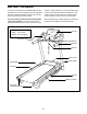
BEFORE YOU BEGIN Thank you for selecting the new PROFORM® 910 ZLT treadmill. The 910 ZLT treadmill provides an impressive selection of features designed to make your workouts at home more effective and enjoyable. manual. To help us assist you, note the product model number and serial number before contacting us. The model number and the location of the serial number decal are shown on the front cover of this manual. For your benefit, read this manual carefully before you use the treadmill.
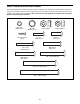
PART IDENTIFICATION CHART Use the drawings below to identify small parts used for assembly. The number in parentheses below each drawing is the key number of the part, from the PART LIST near the end of this manual. The number following the key number is the quantity used for assembly. Note: If a part is not in the hardware kit, check to see if it is preattached. Extra parts may be included.
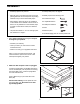
ASSEMBLY • Assembly requires two persons. • To identify small parts, see page 6. • Place all parts in a cleared area and remove the packing materials. Do not dispose of the packing materials until you finish all assembly steps. • Assembly requires the following tools: the included hex keys • After shipping, there may be an oily substance on the exterior of the treadmill. This is normal. If there is an oily substance on the treadmill, wipe it off with a soft cloth and a mild, non-abrasive cleaner.
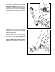
3. Identify the Left Upright (75). Have a second person hold the Left Upright near the Base (80). 3 75 See the inset drawing. Tie the wire tie in the Left Upright (75) securely around the end of the Upright Wire (70). Then, insert the Upright Wire into the lower end of the Left Upright as you pull the other end of the wire tie upward through the Left Upright. Wire Tie 70 Wire Tie 70 75 80 4. With the help of a second person, hold the Left Upright (75) against the Base (80).
5. I dentify the Left and Right Base Covers (73, 74). Slide the Left and Right Base Covers onto the Left and Right Uprights (75, 76) as shown. 5 76 75 74 73 6. Identify the Left Handrail (71). If there is a wire in the Left Handrail, remove and discard it. 6 9 70 Hold the Left Handrail (71) near the Left Upright (75). Insert the wire tie on the Upright Wire (70) into the bottom of the Left Handrail and pull it out of the end of the Left Handrail.
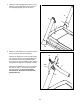
7. Attach the Right Handrail (72) to the Right Upright (76) with two 3/8" x 3 1/2" Screws (9) and two 3/8" Star Washers (5); do not fully tighten the Screws yet. 7 9 5 72 76 8. Insert the Console Frame (87) into the Handrails (71, 72). Attach the Console Frame with four 1/4" x 1" Screws (10). Start all four Screws, and then tighten them. Be careful not to pinch the Upright Wire (not shown). 8 87 9 Firmly tighten the four 3/8" x 3 1/2" Screws (9).
9. With the help of a second person, hold the console assembly near the Left Handrail (71) and the Right Handrail (not shown). 9 Console Assembly Connect the Upright Wire (70) to the console wire. See the inset drawing. The connectors should slide together easily and snap into place. If they do not, turn one connector and try again. IF YOU DO NOT CONNECT THE CONNECTORS PROPERLY, THE CONSOLE MAY BECOME DAMAGED WHEN YOU TURN ON THE POWER. Then, remove the wire tie from the Upright Wire.
11. Attach two Console Clamps (96) to the console assembly with four #8 x 3/4" Screws (6). 11 Console Assembly See step 4. Tighten all six 3/8" x 4" Screws (4). 96 6 12. Identify the Left and Right Trays (97, 85). Orient the Trays as shown, and attach each Tray with four #8 x 3/4" Screws (6). Start all of the Screws, and then tighten them. Be careful not to overtighten the Screws.
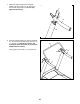
. Raise the Frame (49) to the position shown. Have a second person hold the Frame during the next three assembly steps. 13 Attach the Latch Crossbar (100) to the Frame (49) with two 1/4" x 1 3/4" Screws (107). 49 107 100 14. Orient the Storage Latch (51) so that the large barrel and the latch knob are in the positions shown. Attach the lower end of the Storage Latch (51) to the Base (80) with an M8 x 50mm Bolt (104) and an M8 Nut (108).
15. Attach a Wheel (81) to the Base (80) with a 3/8" x 2 1/2" Bolt (2) and a 3/8" Nut (3). Do not overtighten the Nut; the Wheel must turn freely. Attach the other Wheel (81) to the other side of the Base (80) in the same way. See HOW TO LOWER THE TREADMILL FOR USE on page 25. Lower the Frame (not shown). 15 80 81 3 2 81 16. Make sure that all parts are properly tightened before you use the treadmill. If there are sheets of plastic on the treadmill decals, remove the plastic.
THE CHEST HEART RATE MONITOR HOW TO PUT ON THE HEART RATE MONITOR The heart rate monitor consists of a chest strap and a sensor. Insert the tab on one end of the chest strap into the hole in one end of the sensor as shown. Then, press the end of the sensor under the buckle on the chest strap. The tab should be flush with the front of the sensor.
SP OPERATION AND ADJUSTMENT HOW TO PLUG IN THE POWER CORD Follow the steps below to plug in the power cord. This product must be earthed. If it should malfunction or break down, earthing provides a path of least resistance for electric current to reduce the risk of electric shock. This product’s power cord has an equipment-earthing conductor and an earthing plug. IMPORTANT: If the power cord is damaged, it must be replaced with a manufacturer-recommended power cord. 1.
CONSOLE DIAGRAM FEATURES OF THE CONSOLE You can even listen to your favorite workout music or audio books with the console’s premium stereo sound system while you get in shape. The treadmill console offers an impressive array of features designed to make your workouts more effective and enjoyable. To turn on the power, see page 18. To use the manual mode, see page 18. To use the stereo sound system, see page 20. To use an onboard workout, see page 21. To use an iFit workout, see page 22.
E10812 L10812) HOW TO TURN ON THE POWER HOW TO USE THE MANUAL MODE IMPORTANT: If the treadmill has been exposed to cold temperatures, allow it to warm to room temperature before turning on the power. If you do not do this, you may damage the console displays or other electrical components. 1. Insert the key into the console. Plug in the power cord (see page 16). Next, locate the power switch on the treadmill frame near the power cord. Make sure that the switch is in the reset position.
4. Change the incline of the treadmill as desired. The My Trail tab will show a track that represents 400 m (1/4 mile). As you exercise, the flashing rectangle will show your progress. The My Trail tab will also show the number of laps you complete. To change the incline of the treadmill, press the Incline increase or decrease button or one of the numbered Quick Incline buttons. Each time you press one of the buttons, the treadmill will gradually adjust to the selected incline setting.
6. Measure your heart rate if desired. When you are finished using the treadmill, press the power switch into the off position and unplug the power cord. IMPORTANT: If you do not do this, the treadmill’s electrical components may wear prematurely. Note: If you use the handgrip heart rate monitor and the chest heart rate monitor at the same time, the console will not display your heart rate accurately. For information about the chest heart rate monitor, see page 15.
HOW TO USE AN ONBOARD WORKOUT The workout will continue in this way until the last segment of the profile flashes in the display and the last segment ends. The walking belt will then slow to a stop. 1. Insert the key into the console. See HOW TO TURN ON THE POWER on page 18. Note: The calorie goal is an estimate of the number of calories that you will burn during the workout. The actual number of calories that you burn will depend on various factors such as your weight.
HOW TO USE A SET-A-GOAL WORKOUT 4. Follow your progress with the displays. 1. Insert the key into the console. See HOW TO TURN ON THE POWER on page 18. 5. Measure your heart rate if desired. 2. Select a set-a-goal workout. See step 5 on page 19. See step 6 on page 20. 6. When you are finished exercising, remove the key from the console. To select a set-a-goal workout, press the Set A Goal button on the console.
3. Select a user. 5. Start the workout. I f more than one user is registered, you can switch users in the iFit main screen. Press the increase and decrease buttons next to the Enter button to select a user. During some workouts, the voice of a personal trainer will guide you through your workout. 4. Select an iFit workout. See step 3 on page 21. To stop the workout at any time, press the Stop button. The time will begin to flash in the display.
THE INFORMATION MODE console. However, when you remove the key, the displays will remain lit, although the buttons will not function. If the demo mode is turned on, the word ON will appear in the matrix. To turn on or turn off the demo mode, press the Enter button. The console features an information mode that keeps track of treadmill information and allows you to personalize console settings. 1. Select the information mode.
HOW TO FOLD AND MOVE THE TREADMILL HOW TO FOLD THE TREADMILL HOW TO MOVE THE TREADMILL To avoid damaging the treadmill, adjust the incline to zero before you fold the treadmill. Then, remove the key and unplug the power cord. CAUTION: You must be able to safely lift 45 lbs. (20 kg) to raise, lower, or move the treadmill. Before moving the treadmill, fold it as described at the left. CAUTION: Make sure that the storage latch is locked in the storage position. Moving the treadmill may require two people.
TROUBLESHOOTING Most treadmill problems can be solved by following the simple steps below. Find the symptom that applies, and follow the steps listed. If further assistance is needed, see the front cover of this manual. the key, the demo mode is turned on. To turn off the demo mode, hold down the Stop button for a few seconds. If the displays are still lit, see THE INFORMATION MODE on page 24 to turn off the demo mode.
Locate the Reed Switch (95) and the Magnet (44) on the left side of the Pulley (43). Turn the Pulley until the Magnet is aligned with the Reed Switch. Make sure that the gap between the Magnet and the Reed Switch is about 1/8 in. (3 mm). If necessary, loosen the #8 x 3/4" Truss Head Screw (19), move the Reed Switch slightly, and then retighten the Screw.
SYMPTOM: The walking belt is not centered between the foot rails. IMPORTANT: If the walking belt rubs against the foot rails, the walking belt may be damaged. SYMPTOM: The walking belt slips when walked on a. F irst, remove the key and UNPLUG THE POWER CORD. Using the hex key, turn both idler roller screws clockwise, 1/4 of a turn. When the walking belt is correctly tightened, you should be able to lift each edge of the walking belt 2 to 3 in. (5 to 7 cm) off the walking platform.
EXERCISE GUIDELINES Burning Fat—To burn fat effectively, you must exercise at a low intensity level for a sustained period of time. During the first few minutes of exercise, your body uses carbohydrate calories for energy. Only after the first few minutes of exercise does your body begin to use stored fat calories for energy. If your goal is to burn fat, adjust the intensity of your exercise until your heart rate is near the lowest number in your training zone.
PART LIST Model No. PETL10812.2 R1014A Key No. Qty. Description Key No. Qty.
Key No. Qty. Description Key No. Qty. Description Motor Isolator Motor Bushing Chest Strap M8 x 50mm Bolt #8 Flat Washer 106 107 108 * 1/4" x 1 1/4" Screw 1/4" x 1 3/4" Screw M8 Nut User’s Manual 101 102 103 104 105 1 2 1 1 8 4 2 2 – Note: Specifications are subject to change without notice. For information about ordering replacement parts, see the back cover of this manual. *These parts are not illustrated.
14 32 53 19 29 36 19 25 56 19 38 19 105 36 19 52 14 19 39 105 106 19 19 25 105 19 107 37 106 41 29 40 24 19 105 42 28 108 100 105 19 106 36 19 19 29 107 27 44 36 19 23 12 105 106 43 95 45 19 102 16 1 46 19 50 105 24 101 48 51 27 19 41 32 48 42 28 29 55 35 108 105 47 49 104 1 16 34 1 EXPLODED DRAWING A Model No. PETL10812.
EXPLODED DRAWING B Model No. PETL10812.
EXPLODED DRAWING C Model No. PETL10812.
EXPLODED DRAWING D Model No. PETL10812.
ORDERING REPLACEMENT PARTS To order replacement parts, please see the front cover of this manual.