
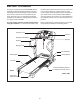
User's Manual

9
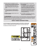
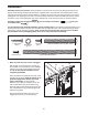
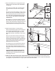
9. Hand tighten four additional Screws (3) into the
console assembly. Then, tighten all nine
Screws used in step 8 and this step; do not
overtighten the Screws.
Console Assembly
3
9
3
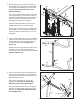
10. Attach the Latch Housing (73) to the left Upright
(84) with two Screws (3). Make sure that the
large hole in the Latch Housing is on the
side shown. Do not overtighten the Screws.
If the pin is not preassembled in the Latch
Housing (73), remove the knob from the pin.
Make sure that the collar and the spring are on
the pin as shown. Insert the pin into the Latch
Housing, and tighten the knob back onto the pin.
Plug in the power cord as described on page 11,
and turn on the power as described on page 13.
Note: The treadmill may automatically rise to the
maximum incline level and then return to the
minimum level.
3
84
10
Knob
Pin
Collar
Large
Hole
Spring
73
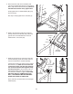
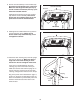
8. Set the console assembly on the Crossbar (20).
Be careful to avoid pinching any of the wires.
M
ake sure that the ground wire (see step 6)
and the console wire harness (see step 7) are
i
nside the indicated channel.
Hand tighten five Screws (3) into the Crossbar
(20) and the console assembly. Start all five
Screws, but do not tighten them yet. Do not
put Screws into the two indicated holes.
Console Assembly
3
3
No Screws
3
20
8
Channel