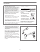
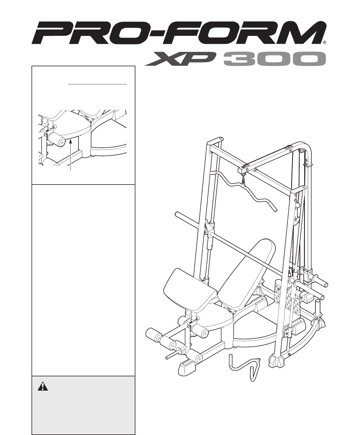
Model No. PFANBE3525.0 Serial No. Write the serial number in the space above for reference. Serial Number Decal (under seat) QUESTIONS? As a manufacturer, we are committed to providing complete customer satisfaction. If you have questions, or if there are missing or damaged parts, please call the telephone number on the warranty card accompanying this manual or contact the establishment where you purchased this product.
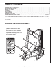
TABLE OF CONTENTS WARNING DECAL PLACEMENT . . . . . . . . . . . . . . . . . . . . . . . . . . . . . . . . . . . . . . . . . . . . . . . . . . . . . . . . . . . . . 2 IMPORTANT PRECAUTIONS . . . . . . . . . . . . . . . . . . . . . . . . . . . . . . . . . . . . . . . . . . . . . . . . . . . . . . . . . . . . . . . . 3 BEFORE YOU BEGIN . . . . . . . . . . . . . . . . . . . . . . . . . . . . . . . . . . . . . . . . . . . . . . . . . . . . . . . . . . . . . . . . . . . . . . 4 ASSEMBLY . . . . . . . . . . . . .
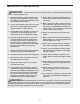
IMPORTANT PRECAUTIONS WARNING: To reduce the risk of serious injury, read the following important precautions before using the weight bench. 1. Read all instructions in this manual and all warnings on the weight bench before using the weight bench. Use the weight bench only as described in this manual. 10. Always make sure that the backrest knob is fully inserted into the backrest frame before exercising. 11. Make sure that the cables remain on the pulleys at all times.
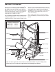
BEFORE YOU BEGIN Thank you for selecting the versatile PROFORM® XP 300 weight bench. The weight bench is designed to help develop every major muscle group of the body. Whether your goal is to tone your body, build dramatic muscle size and strength, or improve your cardiovascular system, the weight bench will help you to achieve the specific results you want. warranty card accompanying this manual. To help us assist you, please note the product model number and serial number before calling.
ASSEMBLY • Tighten all parts as you assemble them, unless instructed to do otherwise. Make Things Easier for Yourself Everything in this manual is designed to ensure that the weight bench can be assembled successfully by anyone. Most people find that setting aside plenty of time helps assembly go smoothly. • For help identifying small parts, use the PART IDENTIFICATION CHART.
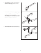
2. Attach the Bench Foot (15) to the Seat Base (1) with two M4 x 16mm Self-tapping Screws (91) and two M4 Washers (84). 2 1 15 84 84 91 3. Insert two M10 x 100mm Screws (26) up through the Base Plate (34), and the Seat Base (1), and the Right and Left Seat Bases (2, 3). 3 2 Attach the Right and Left Seat Bases (2, 3) to the Seat Base (1) with two M10 x 58mm Button Bolts (95) and two M10 Nylon Locknuts (77). 95 1 3 77 34 26 4.
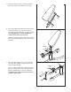
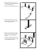
5. Attach the Backrest (11) to the Backrest Frame (8) with four M6 x 15mm Button Screws (17). 5 11 17 8 17 6. Grease the M10 x 87mm Button Bolt (94). Attach the Backrest Frame (8) to the Seat Frame (5) with the Bolt and an M10 Nylon Locknut (77). Do not overtighten the Locknut; the Backrest Frame must be able to pivot easily. 6 Engage the Backrest Frame (8) with the Backrest Knob (22) and fully tighten the Knob into the Seat Frame (5). Grease 8 94 22 77 5 7.
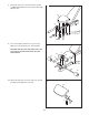
. Attach the Seat (12) to the Seat Frame (5) with four M6 x 63mm Button Screws (92) and four M6 Washers (81). 8 12 5 81 92 92 9. Insert a Pad Tube (10) into the Leg Lever (6). Slide two Foam Pads (14) onto the Pad Tube. 9 Assemble the other two Pad Tubes (10) to the Leg Lever (6) and the Seat Frame (5) in the same manner. 14 5 10 14 6 14 10 10 14 10. Attach the Curl Pad (13) to the Curl Post (7) with two M6 x 15mm Button Screws (17).
11. Attach the Left Rack Base (37) to the Center Rack Base (39) with two M10 x 67mm Bolts (86), an M10 Washer (80), and an M10 Nylon Locknut (77). Do not tighten the Bolts. 11 86 Repeat this step with the Right Rack Base (38). 38 80 39 77 37 12. Attach the Rear Rack Base (40) to the Rear Upright (41) with two M10 x 67mm Bolts (86), two M10 Washers (80), and an M10 Nylon Locknut (77). Do not tighten the Bolts. 12 86 41 77 80 40 13.
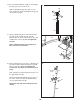
14. Insert the M10 x 20mm Bolt (89) into the Weight Carriage (42) from the side shown. 14 89 Slide the Weight Carriage Stop (58) onto the Rear Upright (41). Slide the Weight Carriage (42) onto the Rear Upright. 42 58 41 15. Attach a Guide Rod (46) to the Left Rack Base (37) with an M8 x 53mm Bolt (9), two M8 Washers (83), an 11mm x 8mm Spacer (82), and an M8 Nylon Locknut (78). Do not tighten the Locknut. 15 38 46 Attach a Guide Rod (46) to the Right Rack Base (38) in the same manner.
17. Attach a Front Upright (43) to the Right Rack Base (38) with two M10 x 82mm Bolts (85), two M10 Washers (80), and an M10 Nylon Locknut (77). Do not tighten the Bolts. 17 88 Attach the Front Upright (43) to the right Guide Rod (46) with an M10 x 25mm Bolt (88). 46 Repeat this step with the other Front Upright (not shown). 43 77 80 38 85 18. Attach the Cross Frame (44) to the right Front Upright (43) with two M10 x 82mm Bolts (85), two M10 Washers (80), and an M10 Nylon Locknut (77).
20. Orient the Locking Bar (50) as shown. Slide the Barbell (51) through the Left Barbell Guide (52), the Locking Bar, and the Right Barbell Guide (53). Make sure that the Barbell is centered in the Barbell Guides. Engage the Locking Bar into the Uprights (43) at the lowest position. 20 53 50 Hole 52 51 43 21. Hand tighten an M8 x 20mm Button Screw (16) into the Left Barbell Guide (52). 21 Slide a Weight Stop (69) onto the Barbell (51). Hand tighten an M6 x 15mm Button Screw (17) into the Weight Stop.
24. Route the Cable (61) under a Pulley (63). Attach the Pulley, a Cable Trap (66), and two Half Finger Guards (65) to the two Pulley Plates (35) with an M10 x 50mm Bolt (79) and an M10 Nylon Locknut (77). Make sure that the Cable Trap is oriented to hold the Cable in the groove of the Pulley. 24 77 61 63 65 65 35 66 79 35 25. Route the Cable (61) over a Pulley (63). Attach the Pulley inside the Top Frame (45) with an M10 x 78mm Bolt (87) and an M10 Nylon Locknut (77). 25 45 77 87 63 61 26.
29. Attach the Cable (61) to the Rear Rack Base (40) with an M10 x 67mm Bolt (86), two M10 Washers (80), and an M10 Nylon Locknut (77). 29 61 77 80 40 80 86 30. Make sure that all parts are properly tightened. The use of the remaining parts will be explained in ADJUSTMENTS, starting below. ADJUSTMENTS This section explains how to adjust the weight bench. See the EXERCISE GUIDELINES on page 18 for important information about how to get the most benefit from your exercise program.
ATTACHING ACCESSORIES The Lat Bar (55) can be attached to a Cable (61) with a Cable Clip (71). For some exercises the Chain (24) should be attached between the Cable and the Lat Bar with two Cable Clips. 61 71 24 The other accessories can be attached to the Cables (61) in the same manner. 71 55 ATTACHING THE BARBELL ADAPTER Slide the Barbell Adapter (54) onto the Barbell (51) and secure it in place with an M8 x 10mm Set Screw (62). Repeat this process on the other side of the Barbell.
ADJUSTING THE BARBELL STOPS 51 Hold the handle on the Barbell Stop Hook (48) and disengage the Hook from the Front Upright (43). Move the Barbell Stop (47) to the lowest point you want the Barbell (51) to go during the exercise. Reengage the Hook into the Upright. Repeat with the other Barbell Stop. 43 48 Handle 47 WARNING: Always set both Barbell Stops (47) at the same height. USING THE BARBELL 51 First, attach the desired amount of weight to the Barbell (51) (see ADDING WEIGHT on the previous page).
CABLE DIAGRAM The cable diagram shows the proper routing of the Cables (61). Use the diagrams to make sure that the cables and the cable traps have been assembled correctly. If the cables have not been correctly routed, the weight bench will not function properly and damage may occur. The numbers show the correct route for each cable. Make sure that the cable traps do not touch or bind the cables.
EXERCISE GUIDELINES THE FOUR BASIC TYPES OF WORKOUTS PERSONALIZING YOUR EXERCISE PROGRAM Muscle Building To increase the size and strength of your muscles, push them close to their maximum capacity. Your muscles will adapt and grow as you progressively increase the intensity of your exercise. You can adjust the intensity level of an individual exercise in two ways: • by changing the amount of weight used • by changing the number of repetitions or sets performed.
slowly as you stretch and do not bounce. Ease into each stretch gradually and go only as far as you can without strain. Stretching at the end of each workout is an effective way to increase flexibility. Rest for a short period of time after each set. The ideal resting periods are: • Rest for three minutes after each set for a muscle building workout. • Rest for one minute after each set for a toning workout. • Rest for 30 seconds after each set for a weight loss workout.
PART IDENTIFICATION CHART Refer to the drawings below to identify small parts used in assembly. The number in parentheses by each drawing is the key number of the part, from the PART LIST in the center of this manual. Note: Some small parts may have been pre-attached. If a part is not in the parts bag, check to see if it has been pre-attached.
PART LIST—Model No. PFANBE3525.0 Key No. Qty.
EXPLODED DRAWING—Model No. PFANBE3525.
EXPLODED DRAWING—Model No. PFANBE3525.
ORDERING REPLACEMENT PARTS To order replacement parts, please call the telephone number on the warranty card accompanying this manual. To help us assist you, be prepared to provide the following information: • the MODEL NUMBER of the product (PFANBE3525.0) • the NAME of the product (PROFORM XP 300 weight bench) • the SERIAL NUMBER of the product (see the front cover of this manual) • the KEY NUMBER and DESCRIPTION of the part(s) (see the PART LIST and EXPLODED DRAWING in the center of this manual) Part No.