Model No. PFCCEL09009.0 Serial No. Write the serial number in the space above for reference. USERʼS MANUAL Serial Number Decal (under frame) QUESTIONS? If you have questions, or if parts are damaged or missing, PLEASE CONTACT OUR CUSTOMER SERVICE DEPARTMENT DIRECTLY. CALL TOLL-FREE: 1-888-936-4266 Mon.–Fri., 7:30 until 16:30 ET (excluding holidays) OR E-MAIL US: customerservice@iconcanada.ca CAUTION Read all precautions and instructions in this manual before using this equipment.
TABLE OF CONTENTS WARNING DECAL PLACEMENT . . . . . . . . . . . . . . . . . . . . . . . . . . . . . . . . . . . . . . . . . . . . . . . . . . . . . . . . . . . . . .2 IMPORTANT PRECAUTIONS . . . . . . . . . . . . . . . . . . . . . . . . . . . . . . . . . . . . . . . . . . . . . . . . . . . . . . . . . . . . . . . .3 BEFORE YOU BEGIN . . . . . . . . . . . . . . . . . . . . . . . . . . . . . . . . . . . . . . . . . . . . . . . . . . . . . . . . . . . . . . . . . . . . . .4 ASSEMBLY . . . . . . . . . . . . .
IMPORTANT PRECAUTIONS WARNING: To reduce the risk of serious injury, read all important precautions and instructions in this manual and all warnings on your elliptical before using your elliptical. ICON assumes no responsibility for personal injury or property damage sustained by or through the use of this product. 1. Before beginning any exercise program, consult your physician. This is especially important for persons over age 35 or persons with pre-existing health problems. 9.
BEFORE YOU BEGIN manual. To help us assist you, note the product model number and serial number before contacting us. The model number and the location of the serial number decal are shown on the front cover of this manual. Thank you for selecting the revolutionary PROFORM® 890 E elliptical. The 890 E elliptical provides an impressive selection of features designed to make your workouts at home more effective and enjoyable. For your benefit, read this manual carefully before you use the elliptical.
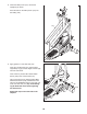
ASSEMBLY Assembly requires two persons. Place all parts of the elliptical in a cleared area and remove the packing materials. Do not dispose of the packing materials until assembly is completed. In addition to the included tool(s), assembly requires a Phillips screwdriver mallet . and a rubber See the drawings below to identify the small parts needed for assembly. The number in parentheses below each drawing is the key number of the part, from the PART LIST near the end of this manual.
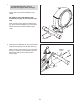
1. 1 To make assembly easier, read the information on page 5 before you begin. Identify and orient the Rear Stabilizer (4) as shown. See HOW TO FOLD AND UNFOLD THE ELLIPTICAL on page 15 and unfold the elliptical. While a second person lifts the Folding Frame (2), attach the Rear Stabilizer (4) to the Folding Frame with two M10 x 95mm Patch Screws (100). 4 2 100 2. Orient the Front Stabilizer (3) so that the welded tubes are facing away from the Main Frame (1).
3. Identify and orient the Upright (5) and the Top Cover (27) as shown. 3 Slide the Top Cover (27) upward onto the Upright (5). Wire Tie Then, have a second person hold the Upright (5) and the Top Cover (27) near the Main Frame (1). Avoid pinching the Wire Harness (60) 5 Locate the wire tie in the Upright (5). Tie the lower end of the wire tie to the Wire Harness (60). Next, pull the upper end of the wire tie until the Wire Harness is routed completely through the Upright.
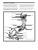
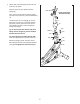
4. Apply a generous amount of the included grease to the Upright Axle (48) and to two Wave Washers (118). 4 60 102 Tip: Avoid damaging the Wire Harness (60). Insert the Upright Axle (48) through the Upright (5) and center it. Slide a Wave Washer (118) onto each side of the Upright Axle. 118 95 7 Next, identify the Right and Left Upper Body Legs (6, 7), which are marked with “Right” and “Left” stickers, and orient them as shown.
6. Apply grease to the axle on the right Crank Arm (39). 6 Orient a Pedal Arm Sleeve (46) so that the flat side is facing the elliptical. Slide the Pedal Arm Sleeve onto the axle on the right Crank Arm (39). Attach the Pedal Arm Sleeve (46) with an M8 x 25mm Patch Screw (121), a Large Axle Cover (113), and an M8 Washer (95). Tip: Avoid damaging the Large Axle Cover when tightening the Patch Screw. Grease Repeat this step on the other side of the elliptical. Flat Side 7. See drawing 7a.
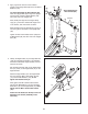
8. Orient the Ramp Cover (131) around the Upright (5) as shown. Press the tabs on the Ramp Cover (131) into the Ramp (130). 8 5 131 130 9. Apply grease to a Link Arm Axle (114). Insert the Link Arm Axle (114) into the Right Upper Body Leg (6) and the Right Link Arm (43) from the side shown. 9 Insert a hex key into the M8 x 35mm Patch Screw (149) in the Link Arm Axle (114).
10. Identify the Right Upper Body Arm (8), which is marked with a “Right” sticker, and orient it as shown. 10 Have a second person hold the Right Upper Body Arm (8) near the Right Upper Body Leg (6). Attach the Right Upper Body Arm (8) to the Right Upper Body Leg (6) with three M8 x 16mm Patch Screws (102) and three M8 Split Washers (103). 9 Attach the Left Upper Body Arm (9) to the Left Upper Body Leg (7) in the same way. 8 7 See step 3 on page 7. Tighten the M8 x 16mm Patch Screws (102).
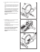
. Remove and discard the wire tie on the Wire Harness (60). While a second person holds the Console (33) near the Upright (5), connect the wires on the Console to the Wire Harness (60), to the Pulse Wires (105), and to the Console Ground Wire (151). 12 33 Tip: Avoid pinching the wires. Finger tighten two M4 x 19mm Screws (156) through the Upright (5) into the upper end of the Console (33). Make sure to start the Screws into the indicated upper holes in the Console.
14..Attach the lower end of the Console (33) to the Upright (5) with two M4 x 19mm Screws (156). See step 12 on page 12. Tighten the M4 x 19mm Screws (156) in the upper end of the Console (33). 14 33 156 15. Orient the Front Upright Cover (24) as shown. Attach the Front Upright Cover (24) around the Upright (5) by pressing the tabs on the Front Upright Cover into the Rear Upright Cover (25). 15 24 25 5 16. Make sure that all parts of the elliptical are properly tightened.
HOW TO USE THE ELLIPTICAL HOW TO PLUG IN THE POWER CORD This product must be grounded. If it should malfunction or break down, grounding provides a path of least resistance for electric current to reduce the risk of electric shock. This product is equipped with a cord having an equipment-grounding conductor and a grounding plug.
HOW TO FOLD AND UNFOLD THE ELLIPTICAL Next, pull the magnets on the pedal arms off the handlebars. Then, lift the latches under the pedal arms, and set the pedal arms on the sleeves on the crank arms. Release the latches, and make sure that the pedal arms are securely connected to the crank arms. When the elliptical is not in use, the frame can be folded out of the way. First, lift the latch under each pedal arm, and lift the pedal arms off the sleeves on the crank arms.
HOW TO EXERCISE ON THE ELLIPTICAL To mount the elliptical, hold the upper body arms and step onto the pedal that is in the lowest position. Next, step onto the other pedal. Push the pedals until they begin to move with a continuous motion. Upper Body Arms Handlebars Note: The crank arms can turn in either direction. It is recommended that you turn the crank arms in the direction shown by the arrow; however, for variety you can turn the crank arms in the opposite direction.
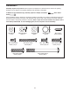
CONSOLE DIAGRAM FEATURES OF THE CONSOLE The console features the iFit interactive workout system, which enables the console to accept iFit cards containing workouts designed to help you achieve specific fitness goals. For example, lose unwanted pounds with the 8-week Weight Loss workout. iFit workouts control the resistance of the pedals while the voice of a personal trainer coaches you through your workouts. iFit cards are available separately. To purchase iFit cards, go to www.iFit.
HOW TO TURN ON THE POWER 3. Change the resistance of the pedals and the incline of the ramp as desired. IMPORTANT: If the elliptical has been exposed to cold temperatures, allow it to warm to room temperature before turning on the power. If you do not do this, you may damage the console displays or other electrical components. Plug in the power cord (see HOW TO PLUG IN THE POWER CORD on page 14). Next, locate the reset/off switch on the frame near the power cord.
The upper display—This display can show the elapsed time, the distance that you have pedaled, your pedaling speed, and the approximate number of calories you have burned. When your pulse is detected, a flashing heart symbol will appear in the display, and then your heart rate will appear. For the most accurate heart rate reading, hold the contacts for at least 15 seconds. Note: If you continue to hold the handgrip pulse sensor, the display will show your heart rate for up to 30 seconds.
HOW TO USE A PRESET WORKOUT As you exercise, keep your pedaling speed near the target speed for the current segment. At the beginning of each segment, the target speed for the segment will flash in the display. 1. Begin pedaling or press any button on the console to turn on the console. See HOW TO TURN ON THE POWER on page 18. 2. Select a preset workout.
HOW TO USE AN IFIT WORKOUT HOW TO USE THE SOUND SYSTEM iFit cards are available separately. To purchase iFit cards, go to www.iFit.com or see the front cover of this manual. iFit cards are also available at select stores. To play music or audio books through the console sound system while you exercise, plug the included audio cable into the jack on the console and into a jack on your MP3 player or CD player; make sure that the audio cable is fully plugged in. 1.
MAINTENANCE AND TROUBLESHOOTING Inspect and tighten all parts of the elliptical regularly. Replace any worn parts immediately. Next, look into the access opening and locate the Reed Switch (69). Rotate the Large Pulley (74) until a Pulley Magnet (75) is aligned with the Reed Switch. To clean the elliptical, use a damp cloth and a small amount of mild soap. IMPORTANT: To avoid damage to the console, keep liquids away from the console and keep the console out of direct sunlight.
HOW TO ADJUST THE DRIVE BELT Loosen the Pivot Screw (97). Tighten the Belt Adjustment Screw (85) until the Drive Belt (38) is tight. When the Drive Belt is tight, tighten the Pivot Screw. If you can feel the pedals slip while you are pedaling, even when the resistance is adjusted to the highest level, the drive belt may need to be adjusted. 38 To adjust the drive belt, first unplug the power cord.
EXERCISE GUIDELINES WARNING: Burning Fat—To burn fat effectively, you must exercise at a low intensity level for a sustained period of time. During the first few minutes of exercise, your body uses carbohydrate calories for energy. Only after the first few minutes of exercise does your body begin to use stored fat calories for energy. If your goal is to burn fat, adjust the intensity of your exercise until your heart rate is near the lowest number in your training zone.
SUGGESTED STRETCHES The correct form for several basic stretches is shown at the right. Move slowly as you stretch—never bounce. 1. Toe Touch Stretch 1 Stand with your knees bent slightly and slowly bend forward from your hips. Allow your back and shoulders to relax as you reach down toward your toes as far as possible. Hold for 15 counts, then relax. Repeat 3 times. Stretches: Hamstrings, back of knees and back. 2. Hamstring Stretch 2 Sit with one leg extended.
NOTES 26
PART LIST Key No. Qty. 1 2 3 4 5 6 7 8 9 10 11 12 13 14 15 16 17 18 19 20 21 22 23 24 25 26 27 28 29 30 31 32 33 34 35 36 37 38 39 40 41 42 43 44 45 46 47 48 49 50 1 1 1 1 1 1 1 1 1 1 1 1 1 1 1 2 2 1 1 1 1 1 6 1 1 1 1 2 18 2 4 2 1 2 2 2 2 1 2 2 3 1 1 2 2 2 2 1 2 2 Description Key No. Qty.
Key No. Qty. 101 102 103 104 105 106 107 108 109 110 111 112 113 114 115 116 117 118 119 120 121 122 123 124 125 126 127 128 129 130 131 132 133 3 16 14 2 2 11 4 6 8 2 4 8 2 2 1 1 1 2 1 1 2 1 1 1 1 2 2 2 3 1 1 4 1 Description Key No. Qty. Small Pedal Arm Snap Ring M8 x 16mm Patch Screw M8 Split Washer Lift Arm Snap Ring Pulse Wire M4 x 16mm Screw M10 x 20mm Button Screw M10 Washer M8 x 16mm Button Screw M8 x 23.
49 52 51 50 31 54 106 154 127 128 54 112 13 95 95 58 62 144 155 54 102 157 53 121 113 95 31 56 103 9 149 30 109 102 35 46 15 54 31 30 112 62 47 111 54 7 54 31 159 54 154 32 12 157 101 11 62 48 34 111 149 14 56 25 158 95 28 26 114 33 103 101 23 57 111 112 62 112 118 102 103 102 47 32 5 151 46 155 58 54 54 23 24 43 6 54 50 54 149 52 127 128 53 103 35 102 56 8 106 95 34 59 54 102 102 51 95 103 10 5
73 86 30 41 37 75 100 4 116 129 125 97 39 115 96 94 99 2 41 76 150 75 98 150 87 74 72 70 85 68 80 69 106 82 90 161 91 61 55 37 71 87 88 84 133 122 94 60 83 101 135 148 108 78 89 107 145 117 119 76 160 77 92 81 79 38 67 86 39 147 108 86 29 64 42 66 109 110 132 107 132 29 131 124 41 132 29 65 64 134 137 29 130 120 106 140 146 36 44 108 3 1 123 141 100 139 104 136 102 16 143 126 108 107 45 44 102 103 40 93
17 29 153 152 29 20 153 23 152 152 19 22 152 152 29 153 152 152 29 21 31 153 18 29 152 17 152 152 EXPLODED DRAWING C Model No. PFCCEL09009.
ORDERING REPLACEMENT PARTS To order replacement parts, see the front cover of this manual.