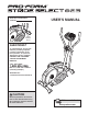
Model No. PFCCEL3906.2 Serial No. _ USER’S MANUAL Serial Number Decal QUESTIONS? As a manufacturer, we are committed to providing complete customer satisfaction. If you have questions, or if parts are damaged or missing, PLEASE CONTACT OUR CUSTOMER SERVICE DEPARTMENT DIRECTLY. CALL TOLL-FREE: 1-888-936-4266 Mon.–Fri., 8:00 until 17:00 EST (excluding holidays) OR E-MAIL US: customerservice@iconcanada.ca CAUTION Read all precautions and instructions in this manual before using this equipment.
TABLE OF CONTENTS IMPORTANT PRECAUTIONS . . . . . . . . . . . . . . . . . . . . . . . . . . . . . . . . . . . . . . . . . . . . . . . . . . . . . . . . . . . . . . . .3 BEFORE YOU BEGIN . . . . . . . . . . . . . . . . . . . . . . . . . . . . . . . . . . . . . . . . . . . . . . . . . . . . . . . . . . . . . . . . . . . . . .4 ASSEMBLY . . . . . . . . . . . . . . . . . . . . . . . . . . . . . . . . . . . . . . . . . . . . . . . . . . . . . . . . . . . . . . . . . . . . . . . . . . . . . . .
IMPORTANT PRECAUTIONS WARNING: To reduce the risk of serious injury, read the following important precautions before using the elliptical exerciser. 1. Read all instructions in this manual and all warnings on the elliptical exerciser before using the elliptical exerciser. Use the elliptical exerciser only as described in this manual. 10. The pulse sensor is not a medical device. Various factors may affect the accuracy of heart rate readings.
BEFORE YOU BEGIN Congratulations for selecting the new PROFORM® STRIDE SELECT 825 elliptical exerciser. The STRIDE SELECT 825 is an incredibly smooth exerciser that moves your feet in a natural elliptical path, minimizing the impact on your knees and ankles. And the unique STRIDE SELECT 825 offers an impressive array of features to help you achieve your fitness goals in the convenience of your home. cover of this manual.
ASSEMBLY To hire an authorized service technician to assemble the elliptical exerciser, call toll-free 1-800-445-2480. Assembly requires two persons. Place all parts of the elliptical exerciser in a cleared area and remove the packing materials. Do not dispose of the packing materials until assembly is completed. In addition to the included allen wrenches, assembly requires a phillips screwdriver , an adjustable wrench , and a rubber mallet .
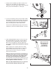
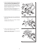
1. Identify the Rear Stabilizer (4). While another person lifts the rear of the Frame (1), attach the Rear Stabilizer to the Frame with two M10 x 75mm Carriage Bolts (34) and two M10 Nylon Locknuts (29). 1 29 1 29 2. See the inset drawing. Remove the two M10 x 45mm Button Bolts (33) and the packing tubes from the front of the Frame (1). Next, remove the rubber band from the Lower Wire Harness (87). Discard the Button Bolts, the packing tubes, and the rubber band.
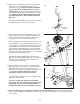
4. While another person holds the Upright (2) in the position shown, connect the Upper Wire Harness (86) to the Extension Wire Harness (95). 4 Next, insert the Upright (2) into the Mast (15); make sure that the Upright is oriented as shown. Attach the Upright with two M8 x 70mm Button Bolts (67), two M8 Split Washers (83), and two M8 Nylon Locknuts (46). Make sure that the Wire Harnesses (86, 95) do not get pinched and damaged during this step. Do not tighten the Button Bolts yet.
7. Slide the Right Crank Arm (38) onto the four indicated welded bolts; make sure that the Right Crank Arm is in the indicated cutout in the Pedal Disk (8). Next, finger tighten four M8 Jamnuts (80) onto the welded bolts. Then, fully tighten one of the Jamnuts, and then tighten the Jamnut farthest from the first Jamnut. Then, tighten the remaining two Jamnuts. 7 Welded Bolts Attach a Hub Cover (48) to the Right Crank Arm (38) with four Cover Screws (82).
10. Identify the Left Handlebar (9), which is marked with a sticker. Insert the Left Handlebar into one of the Handlebar Legs (79); make sure that the Handlebar Leg is turned so the hexagonal holes are on the indicated side. Attach the Left Handlebar with two M8 x 45mm Button Bolts (50) and two M8 Nylon Locknuts (46). Make sure that the Nylon Locknuts are inside of the hexagonal holes. Do not tighten the Button Bolts yet.
HOW TO USE THE ELLIPTICAL EXERCISER HOW TO EXERCISE ON THE ELLIPTICAL EXERCISER HOW TO USE THE HANDLEBARS To dismount the elliptical exerciser, wait until the pedals come to a complete stop. Note: The elliptical exerciser does not have a free wheel; the pedals will continue to move until the flywheel stops. When the pedals are stationary, step off the highest pedal first. Then, step off the lowest pedal. To exercise only your lower body, hold the handgrip pulse sensor as you exercise.
DIAGRAM OF THE CONSOLE Fan Button Increase Button Program Profiles Program Button Program Indicator Display FEATURES OF THE CONSOLE Pace Guide Decrease Button HOW TO USE THE MANUAL MODE The advanced console offers a selection of features designed to make your workouts more effective. When the manual mode of the console is selected, the resistance of the pedals can be changed with the touch of a button. As you pedal, the console will provide continuous exercise feedback.
4 5 For the most accurate heart rate reading, continue to hold the handgrip pulse sensor for about 30 seconds. Note: If you continue to hold the handgrip pulse sensor, the display will show your heart rate for about 30 seconds. The display will then show your heart rate along with the other modes. Monitor your progress with the display. The upper half of the display will show the elapsed time, the distance (total revolutions) you have pedaled, and the resistance level of the pedals.
5 HOW TO USE A PULSE PROGRAM Pulse program 1 is designed to keep your heart rate within a set range during your workout. Pulse program 2 is designed to keep your heart rate near a target heart rate setting that you select. Follow the steps below to use a pulse program. 1 2 3 4 Begin pedaling to start the program. Pulse program 1 is 30 minutes long, and is divided into several time periods of different lengths. One target heart rate is programmed for each period.
7 8 Turn on the fan if desired. seconds. The resistance of the pedals will then automatically change to the resistance level that is programmed for the next period. Note: If the resistance level is too high or too low, you can override it by pressing the Increase and Decrease buttons. However, when the current period ends, the resistance level will automatically change if a different resistance level is programmed for the next period. See step 6 on page 12.
MAINTENANCE AND TROUBLESHOOTING HANDGRIP PULSE SENSOR TROUBLESHOOTING Inspect and tighten all parts of the elliptical exerciser regularly. Replace any worn parts immediately. • Avoid moving your hands while using the handgrip pulse sensor. Excessive movement may interfere with heart rate readings. To clean the elliptical exerciser, use a damp cloth and a small amount of mild soap. Important: To avoid damage to the console, keep liquids away from the console and keep the console out of direct sunlight.
CONDITIONING GUIDELINES WARNING: Before beginning this or any exercise program, consult your physician. This is especially important for persons over the age of 35 or persons with pre-existing health problems. The pulse sensor is not a medical device. Various factors may affect the accuracy of heart rate readings. The pulse sensor is intended only as an exercise aid in determining heart rate trends in general.
PART LIST—Model No. PFCCEL3906.2 Key No. Qty.
EXPLODED DRAWING A—Model No. PFCCEL3906.
EXPLODED DRAWING B—Model No. PFCCEL3906.
HOW TO ORDER REPLACEMENT PARTS To order replacement parts, see the front cover of this manual. To help us assist you, please be prepared to give the following information when calling: • the MODEL NUMBER of the product (PFCCEL3906.2) • the NAME of the product (PROFORM STRIDE SELECT 825 elliptical exerciser) • the SERIAL NUMBER of the product (see the front cover of this manual) • the KEY NUMBER and DESCRIPTION of the part(s) (see pages 17 to 19) LIMITED WARRANTY ICON OF CANADA, INC.