proform.com Model No. PFEL03815.7 Serial No. Write the serial number in the space above for reference. Serial Number Decal ACTIVATE YOUR WARRANTY To register your product and activate your warranty today, go to my.proform.com. CUSTOMER CARE For service at any time, go to proformservice.com. Or call 1-888-533-1333 Mon.–Fri. 6 a.m.–6 p.m. MT Sat. 8 a.m.–12 p.m. MT Please do not contact the store. CAUTION Read all precautions and instructions in this manual before using this equipment.
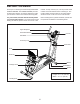
TABLE OF CONTENTS WARNING DECAL PLACEMENT . . . . . . . . . . . . . . . . . . . . . . . . . . . . . . . . . . . . . . . . . . . . . . . . . . . . . . . . . . . . . . .2 IMPORTANT PRECAUTIONS. . . . . . . . . . . . . . . . . . . . . . . . . . . . . . . . . . . . . . . . . . . . . . . . . . . . . . . . . . . . . . . . . . 3 BEFORE YOU BEGIN. . . . . . . . . . . . . . . . . . . . . . . . . . . . . . . . . . . . . . . . . . . . . . . . . . . . . . . . . . . . . . . . . . . . . . . .5 PART IDENTIFICATION CHART.
IMPORTANT PRECAUTIONS WARNING: To reduce the risk of serious injury, read all important precautions and instructions in this manual and all warnings on your hybrid trainer before using your hybrid trainer. ICON assumes no responsibility for personal injury or property damage sustained by or through the use of this product. 1. It is the responsibility of the owner to ensure that all users of the hybrid trainer are adequately informed of all precautions. 9.
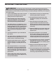
STANDARD SERVICE PLANS all 4
BEFORE YOU BEGIN Thank you for selecting the revolutionary PROFORM® HYBRID TRAINER. The HYBRID TRAINER provides an impressive selection of features designed to make your workouts at home more effective and enjoyable. manual. To help us assist you, note the product model number and serial number before contacting us. The model number and the location of the serial number decal are shown on the front cover of this manual. For your benefit, read this manual carefully before you use the hybrid trainer.
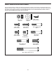
PART IDENTIFICATION CHART Use the drawings below to identify the small parts needed for assembly. The number in parentheses below each drawing is the key number of the part, from the PART LIST near the end of this manual. The number following the key number is the quantity needed for assembly. Note: If a part is not in the hardware kit, check to see if it has been preassembled. Extra parts may be included.
ASSEMBLY • To hire an authorized service technician to assemble the hybrid trainer, call 1-800-445-2480. • In addition to the included tool(s), assembly requires the following tools: • Assembly requires two persons. one Phillips screwdriver • Place all parts in a cleared area and remove the packing materials. Do not dispose of the packing materials until you finish assembly. one adjustable wrench • Left parts are marked “L” or “Left” and right parts are marked “R” or “Right.
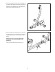
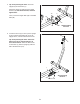
3. Orient the Upright (2) and the Front Stabilizer (5) so that the large holes (B) are facing the Upright. 3 Attach the Front Stabilizer (5) to the Upright (2) with two M10 x 80mm Screws (19). 19 5 2 B 4. Set the Upright (2) near the Frame (1) as shown. 4 Locate the wire tie in (C) the Frame (1) and pull the Main Wire (96) out of the underside of the Frame. Repeat this action to pull the Upper Wire (not shown) out of the underside of the Upright (2).
5. Tip: Avoid pinching the wires. Insert the Upright (2) into the Frame (1). 5 Attach the Upright (2) with six M10 x 20mm Screws (76); start all the Screws, and then tighten them. 2 76 Then, connect the Upper Wire (94) to the Main Wire (96). 76 1 94 96 6. Locate the wire tie (D) in the top of the Upright (2) and pull the Upper Wire (94) out of the Upright. Then, untie and discard the wire tie. 76 6 Avoid pinching the wires 94 Tip: Avoid pinching the wires.
7. Have a second person hold the Pivot Bracket (3) near the Upright (2). 7 F Locate the wire tie (F) in the Pivot Bracket (3). Tie the wire tie to the Upper Wire (94) and then pull the other end of the wire tie until the Upper Wire is routed through the Pivot Bracket. 3 94 F 2 8. Using a plastic bag to keep your fingers clean, apply a generous amount of the included grease to the Pivot Axle (80). 8 Tip: Avoid pinching the Upper Wire (94).
9. Identify the Right Pedal (70) and the Right Pedal Arm (9), and orient them as shown. 9 70 105 72 Attach the Right Pedal (70) to the right Pedal Plate (72) with four M6 x 15mm Screws (105); start all the Screws, and then tighten them. Repeat this step for the Left Pedal (not shown) and the Left Pedal Arm (not shown). 105 9 10. Identify the Right Pedal Arm (9) and the Right Pivot Leg (8), and orient them as shown.
11. Slide a Pivot Spacer (79) onto each side of the Pivot Axle (80). 11 Then, slide the Right and Left Pivot Legs (8, 11) onto the Pivot Axle (80); make sure that the Pivot Legs are on the correct sides. 86 Then, tighten an M8 x 14mm Shoulder Screw (86), with a Pivot Cover (83) and an M8 Washer (87), into each end of the Pivot Axle (80) at the same time. 83 80 87 11 79 79 87 8 12. Remove and discard the packaging on the Right Crank Bracket (30).
. The Console (4) requires four D batteries (not included); alkaline batteries are recommended. Do not use old and new batteries together or alkaline, standard, and rechargeable batteries together. IMPORTANT: If the Console has been exposed to cold temperatures, allow it to warm to room temperature before inserting batteries. Otherwise, you may damage the console displays or other electronic components.
15. Identify the Right Upper Body Arm (7). 15 Orient an Upper Body Cover (78) as shown, and slide it upward onto the Right Upper Body Arm (7). Attach the Right Upper Body Arm (7) to the Right Pivot Leg (8) with three M8 x 38mm Hex Bolts (102) and three M8 Locknuts (68); start all the Hex Bolts, and then tighten them. Make sure that the Locknuts are inside the hexagonal holes (H). 7 78 68 H Then, slide the Upper Body Cover (78) downward onto the Right Pivot Leg (8).
17. Attach the Seat Frame (61) to the Seat Carriage (32) with four M6 x 35mm Screws (98); start all the Screws, and then tighten them. 17 98 98 61 32 18. Attach the Seat (28) to the Seat Frame (61) with four M6 x 20mm Screws (97) (only two are shown); start all the Screws, and then tighten them.
19. IMPORTANT: You must activate your Console (4) to begin using its exclusive features. 19 First, press any button on the Console (4) to turn on the power. 4 Then, using your smart phone or tablet, go to iFit.com/activate and follow the instructions to activate the Console (4). Note: If you do not have a smart phone or tablet, use your computer to go to iFit.com/activate for an alternate way to activate the Console (4).
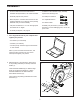
HOW TO USE THE HYBRID TRAINER HOW TO MOVE THE HYBRID TRAINER HOW TO USE THE TABLET HOLDER Lift the rear stabilizer (A) until the hybrid trainer will roll on the wheels. Carefully move the hybrid trainer to the desired location, and then lower it to the floor. IMPORTANT: The tablet holder (C) is designed for use with most full-size tablets and smartphones. Do not place any other electronic device or object into the tablet holder.
HOW TO USE THE RECUMBENT BIKE MODE To mount the hybrid trainer in the elliptical mode, hold the handlebars (F) or the upper body arms (G) and step onto the pedal (H) that is in the lower position. Then, step onto the other pedal. To use the hybrid trainer as a recumbent bike, loosen the pivot knob (D) and pivot the pivot bracket to the low position. G F D Next, lift a pedal, unfold the brace (E), and insert the end of the brace into the pedal arm (J).
CONSOLE DIAGRAM FEATURES OF THE CONSOLE IMPORTANT: To activate your console and begin using its exclusive features, see assembly step 19 on page 16. The advanced console offers an array of features designed to make your workouts more effective and enjoyable. When you use the manual mode of the console, you can change the resistance of the pedals with the touch of a button. As you exercise, the console will provide continuous exercise feedback.
HOW TO USE THE MANUAL MODE The upper display—This display will show your pedaling speed in revolutions per minute (RPM) and your power output in watts. The display will change every few seconds. 1. Turn on the console. Press any button or begin pedaling to turn on the console. When you turn on the console, the displays will turn on, a tone will sound, and the console will be ready for use.
To pause the console, stop pedaling. When the console is paused, the displays will pause. To continue your workout, simply resume pedaling. When your pulse is detected, your heart rate will be shown in the upper display. For the most accurate heart rate reading, hold the contacts for at least 15 seconds. To reset the displays to zero, press the On/Reset button. If your heart rate is not shown, make sure that your hands are positioned as described.
HOW TO USE A PRESET WORKOUT The speed meter will show two flashing bars B that represent the target speed zone (B) for the segment; the target speed zone includes a range of speeds that are within a few RPMs of the target speed for the segment. The solid bars represent your actual pedaling speed. 1. Turn on the console. Press any button or begin pedaling to turn on the console. When you turn on the console, the displays will turn on, a tone will sound, and the console will be ready for use. 2.
THE OPTIONAL CHEST HEART RATE MONITOR 3. Connect your tablet to the console. Whether your goal is to burn fat or to strengthen your cardiovascular system, the key to achieving the best results is to maintain the proper heart rate during your workouts. The optional chest heart rate monitor will enable you to continuously monitor your heart rate while you exercise, helping you to reach your personal fitness goals. To purchase a chest heart rate monitor, please see the front cover of this manual.
THE SETTINGS MODE unit of measurement, press the Elliptical Workouts button repeatedly. The console features a settings mode that allows you to select a unit of measurement for the console and to view console usage information. Note: When you replace the batteries, it may be necessary to reselect the unit of measurement. To select the settings mode, press and hold down the On/Reset button until the settings mode information appears in the display.
MAINTENANCE AND TROUBLESHOOTING MAINTENANCE Next, locate the Reed Switch (60). Slightly loosen the two M4 x 19mm Screws (84). Regular maintenance is important for optimal performance and to reduce wear. Inspect and properly tighten all parts each time the hybrid trainer is used. Replace any worn parts immediately. 117 To clean the hybrid trainer, use a damp cloth and a small amount of mild soap.
HOW TO ADJUST THE DRIVE BELT Next, loosen the M10 x 55mm Bolt (99). Then, tighten the M8 Locknut (68) until the Drive Belt (64) is tight. If you can feel the pedals slip while you are pedaling, even when the resistance is adjusted to the highest level, the drive belt may need to be adjusted. 68 To adjust the drive belt, first remove the M4 x 19mm Self-tapping Screw (100) from the Side Access Cover (21), and then remove the Side Access Cover by moving it in the direction shown by the arrow.
EXERCISE GUIDELINES Burning Fat—To burn fat effectively, you must exercise at a low intensity level for a sustained period of time. During the first few minutes of exercise, your body uses carbohydrate calories for energy. Only after the first few minutes of exercise does your body begin to use stored fat calories for energy. If your goal is to burn fat, adjust the intensity of your exercise until your heart rate is near the lowest number in your training zone.
PART LIST Key No. Qty. 1 2 3 4 5 6 7 8 9 10 11 12 13 14 15 16 17 18 19 20 21 22 23 24 25 26 27 28 29 30 31 32 33 34 35 36 37 38 39 40 41 42 43 44 45 46 47 48 49 50 1 1 1 1 1 1 1 1 1 1 1 1 1 1 2 2 2 2 4 1 1 1 1 2 1 1 1 1 2 1 2 1 2 1 2 1 1 1 4 4 2 2 1 1 1 1 1 2 1 1 Model No. PFEL03815.7 R1217A Description Key No. Qty.
Key No. Qty. 101 102 103 104 105 106 107 108 109 110 2 6 1 1 8 6 2 1 2 1 Description Key No. Qty.
12 71 10 20 78 11 15 30 17 85 13 25 3 115 77 65 82 116 84 14 79 75 5 84 2 84 19 17 80 115 16 16 65 85 4 101 82 94 96 68 68 106 81 79 104 103 65 87 106 8 65 78 102 102 7 83 9 86 68 105 68 15 75 74 86 109 87 107 83 105 65 73 105 84 72 70 EXPLODED DRAWING A Model No. PFEL03815.
92 24 66 31 42 117 64 48 19 91 51 42 108 84 62 45 47 88 44 46 93 90 60 88 84 63 68 50 84 84 112 68 117 100 26 21 89 6 49 112 62 92 100 116 51 52 85 84 99 1 22 51 84 43 59 84 91 89 114 51 40 24 53 68 65 39 40 97 61 55 83 112 87 68 56 113 51 35 32 111 65 57 110 30 18 87 51 29 56 113 76 69 69 58 76 67 18 84 23 84 41 86 68 48 41 95 39 92 54 39 36 112 34 98 29 92 38 68 37 27 64 31 28 33 EXPLODED DRAWING B Mod
ORDERING REPLACEMENT PARTS To order replacement parts, please see the front cover of this manual.