proform.com Model No. PFEL03916.2 Serial No. Write the serial number in the space above for reference. Serial Number Decal ACTIVATE YOUR WARRANTY To register your product and activate your warranty today, go to my.proform.com. CUSTOMER CARE For service at any time, go to proformservice.com. Or call 1-888-533-1333 Mon.–Fri. 6 a.m.–6 p.m. MT Sat. 8 a.m.–12 p.m. MT Please do not contact the store. CAUTION Read all precautions and instructions in this manual before using this equipment.
TABLE OF CONTENTS WARNING DECAL PLACEMENT . . . . . . . . . . . . . . . . . . . . . . . . . . . . . . . . . . . . . . . . . . . . . . . . . . . . . . . . . . . . . . .2 IMPORTANT PRECAUTIONS. . . . . . . . . . . . . . . . . . . . . . . . . . . . . . . . . . . . . . . . . . . . . . . . . . . . . . . . . . . . . . . . . . 3 BEFORE YOU BEGIN. . . . . . . . . . . . . . . . . . . . . . . . . . . . . . . . . . . . . . . . . . . . . . . . . . . . . . . . . . . . . . . . . . . . . . . .5 PART IDENTIFICATION CHART.
IMPORTANT PRECAUTIONS WARNING: To reduce the risk of serious injury, read all important precautions and instructions in this manual and all warnings on your elliptical before using your elliptical. ICON assumes no responsibility for personal injury or property damage sustained by or through the use of this product. 1. It is the responsibility of the owner to ensure that all users of the elliptical are adequately informed of all precautions. 9.
STANDARD SERVICE PLANS 4
BEFORE YOU BEGIN Thank you for selecting the revolutionary PROFORM® 250 I elliptical. The 250 I elliptical provides an impressive selection of features designed to make your workouts at home more effective and enjoyable. manual. To help us assist you, note the product model number and serial number before contacting us. The model number and the location of the serial number decal are shown on the front cover of this manual. For your benefit, read this manual carefully before you use the elliptical.
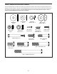
PART IDENTIFICATION CHART Use the drawings below to identify the small parts needed for assembly. The number in parentheses below each drawing is the key number of the part, from the PART LIST near the end of this manual. The number following the key number is the quantity needed for assembly. Note: If a part is not in the hardware kit, check to see if it has been preassembled. Extra parts may be included.
ASSEMBLY • To hire an authorized service technician to assemble this product, call 1-800-445-2480. • To identify small parts, see page 6. • In addition to the included tool(s), assembly requires the following tools: • Assembly requires two persons. one Phillips screwdriver • Place all parts in a cleared area and remove the packing materials. Do not dispose of the packing materials until you finish all assembly steps. Assembly may be easier if you have a set of wrenches.
3. With the help of a second person, place some of the packing materials (not shown) under the rear of the Frame (1). 3 Attach the Track (11) to the Frame (1) with four M10 x 20mm Screws (74), two M10 x 38mm Screws (75), and six M10 Washers (64) as shown; start all of the Screws, and then tighten them. 74 1 64 74 11 64 Then, remove the packing materials from under the Frame (1). 75 4. Orient the Upright (2) and the Accessory Tray (50) as shown. Slide the Accessory Tray upward onto the Upright.
5. Tip: Avoid pinching the Main Wire (32). Slide the Upright (2) onto the Frame (1). 5 Attach the Upright (2) with three M10 x 20mm Screws (74), three M10 Split Washers (80), and three M10 Curved Washers (62) as shown; do not fully tighten the Screws yet. Avoid pinching the Main Wire (32) Finish attaching the Upright (2) with an M10 x 60mm Bolt (72) and an M10 Small Locknut (91); do not fully tighten the Bolt yet. Make sure that the Small Locknut is in the hexagonal hole (B).
7. Identify the Right Upper Body Arm (3) and the Right Upper Body Leg (5), and orient them as shown. 7 Insert the Right Upper Body Arm (3) into the Right Upper Body Leg (5). Attach the Right Upper Body Arm with three M8 x 38mm Bolts (59) and three M8 Locknuts (60); make sure that the Locknuts are in the hexagonal holes (C). Start all of the Bolts, and then tighten them. 3 4 Attach the Left Upper Body Arm (4) to the Left Upper Body Leg (6) in the same way. 60 6 C 60 59 59 5 8.
9. Identify a set of Pivot Covers A and B (85, 86) and orient them as shown. 9 Press the Pivot Covers A and B (85, 86) together around the Right Upper Body Arm (3) and the Right Upper Body Leg (5), and attach them with four M4 x 16mm Self-tapping Screws (57); start all of the Self-tapping Screws, and then tighten them. 3 Repeat this step on the other side of the elliptical. 86 85 57 5 57 10. Identify the Front and Rear Upright Covers (51, 54) and orient them as shown.
11. Apply grease to the right Crank Arm (13). 11 Identify the Right Roller Arm (7) and orient it as shown. Attach the Right Roller Arm (7) to the right Crank Arm (13) with an M8 x 20mm Screw (61), an Axle Cover (44), and an M8 Washer (63). Grease 13 Attach the Left Roller Arm (8) in the same way. 63 8 44 61 7 12. Apply grease to the axle on the Right Roller Arm (7). 12 Then, identify the Right Pedal Arm (9), orient it as shown, and slide it onto the Right Roller Arm (7).
. Apply grease to an M6 Bolt Set (67). 13 Attach the Right Pedal Arm (9) to the Right Upper Body Leg (5) with the M6 Bolt Set (67). 6 Attach the Left Pedal Arm (10) to the Left Upper Body Leg (6) in the same way. 10 5 67 9 67 Grease 14. The Console (30) can use four D batteries (not included); alkaline batteries are recommended. Do not use old and new batteries together or alkaline, standard, and rechargeable batteries together.
15. Attach the Tablet Holder (92) to the back of the Console (30) with four Tablet Holder Screws (73); start all of the Tablet Holder Screws, and then tighten them. 15 92 73 30 16. Remove and discard the wire tie on the Main Wire (32). 16 While a second person holds the Console (30) near the Upright (2), plug the Main Wire (32) and the Pulse Wire (31) into the matching receptacles on the back of the Console.
17. IMPORTANT: You must activate your Console (30) to begin using its exclusive features. 17 First, press any button on the Console (30) to turn on the power. 30 Then, using your smart phone or tablet, go to iFit.com/activate and follow the instructions to activate the Console (30). Note: If you do not have a smart phone or tablet, use your computer to go to iFit.com/activate for an alternate way to activate the Console (30).
HOW TO USE THE ELLIPTICAL HOW TO MOVE THE ELLIPTICAL HOW TO LEVEL THE ELLIPTICAL Due to the size and weight of the elliptical, moving it requires two persons. Stand in front of the elliptical, hold the upright (A), and place one foot against one of the wheels (B). Pull on the upright, and have a second person lift the track (C) until the elliptical will roll on the wheels. Carefully move the elliptical to the desired location, and then lower it to the floor.
HOW TO EXERCISE ON THE ELLIPTICAL G To mount the elliptical, hold the handlebars (F) or the upper body arms (G) and step onto the pedal (H) that is in the lower position. Then, step onto the other pedal. Push the pedals until they begin to move with a continuous motion. Note: The pedals can turn in either direction. It is recommended that you turn the pedals in the direction shown by the arrow; however, for variety, you can turn the pedals in the opposite direction.
CONSOLE DIAGRAM FEATURES OF THE CONSOLE IMPORTANT: To activate your console and begin using its exclusive features, see assembly step 17 on page 15. The console also offers a selection of preset workouts. Each preset workout automatically changes the resistance of the pedals and prompts you to maintain a target speed as it guides you through an effective workout. The advanced console offers an array of features designed to make your workouts more effective and enjoyable.
HOW TO USE THE MANUAL MODE The upper display—This display will show your pedaling speed in revolutions per minute (RPM) and your power output in watts. The display will change every few seconds. 1. Turn on the console. Press any button or begin pedaling to turn on the console. When you turn on the console, the displays will turn on, a tone will sound, and the console will be ready for use.
To pause the console, stop pedaling. When the console is paused, the displays will pause. To continue your workout, simply resume pedaling. When your pulse is detected, your heart rate will be shown in the upper display. For the most accurate heart rate reading, hold the contacts for at least 15 seconds. To reset the displays to zero, press the On/Reset button. Note: The console can show pedaling speed and distance in either miles or kilometers.
HOW TO USE AN 8-WEEK WEIGHT-LOSS WORKOUT The speed meter will B show two flashing bars that represent the target speed zone (B) for the segment; the target speed zone includes a range of speeds that are within a few RPMs of the target speed for the segment. The solid bars represent your actual pedaling speed. 1. Turn on the console. Press any button or begin pedaling to turn on the console.
HOW TO USE A PRESET WORKOUT As you exercise, keep your pedaling speed within the target zone for the current segment by increasing or decreasing your pedaling speed or by increasing or decreasing the resistance of the pedals. 1. Turn on the console. Press any button or begin pedaling to turn on the console. IMPORTANT: The target speed is intended only to provide motivation. Make sure to pedal at a speed and a resistance level that is comfortable for you.
HOW TO USE THE SOUND SYSTEM HOW TO CONNECT YOUR TABLET TO THE CONSOLE To play music or audio books through the console sound system while you exercise, plug a 3.5 mm male to 3.5 mm male audio cable (not included) into the jack on the console and into a jack on your personal audio player; make sure that the audio cable is fully plugged in. Note: To purchase an audio cable, see your local electronics store.
5. Disconnect your tablet from the console if desired. THE SETTINGS MODE The console features a settings mode that allows you to select a unit of measurement for the console and to view console usage information. To disconnect your tablet from the console, first select the disconnect option in the iFit Bluetooth Tablet app. Then, press and hold the iFit Sync button on the console until the LED on the console turns solid green.
FCC INFORMATION This equipment has been tested and found to comply with the limits for a Class B digital device, pursuant to Part 15 of the FCC Rules. These limits are designed to provide reasonable protection against harmful interference in a residential installation. This equipment generates, uses, and can radiate radio frequency energy and, if not installed and used in accordance with the instructions, may cause harmful interference to radio communications.
MAINTENANCE AND TROUBLESHOOTING MAINTENANCE HOW TO ADJUST THE REED SWITCH Regular maintenance is important for optimal performance and to reduce wear. Inspect and properly tighten all parts each time the elliptical is used. Replace any worn parts immediately. If the console does not display correct feedback, the reed switch should be adjusted. To adjust the reed switch, first use a standard screwdriver and carefully pry the Accessory Tray (50) upward off the Right and Left Shields (48, 49).
HOW TO ADJUST THE DRIVE BELT See EXPLODED DRAWING A on page 30. Identify the Right and Left Shields (48, 49). Remove the M4 x 16mm Screws (56) and the M4 x 16mm Selftapping Screws (57) from the Right and Left Shields; make sure to note the location of each Screw. Then, gently remove the Right Shield. If the pedals slip while you are pedaling, even while the resistance is adjusted to the highest level, the drive belt may need to be adjusted.
EXERCISE GUIDELINES Burning Fat—To burn fat effectively, you must exercise at a low intensity level for a sustained period of time. During the first few minutes of exercise, your body uses carbohydrate calories for energy. Only after the first few minutes of exercise does your body begin to use stored fat calories for energy. If your goal is to burn fat, adjust the intensity of your exercise until your heart rate is near the lowest number in your training zone.
PART LIST Key No. Qty. 1 2 3 4 5 6 7 8 9 10 11 12 13 14 15 16 17 18 19 20 21 22 23 24 25 26 27 28 29 30 31 32 33 34 35 36 37 38 39 40 41 42 43 44 45 46 47 48 1 1 1 1 1 1 1 1 1 1 1 1 2 1 1 2 4 1 4 1 3 2 1 1 1 1 1 2 1 1 1 1 1 2 1 4 4 4 2 2 2 2 2 4 2 1 1 1 Model No. PFEL03916.2 R0118A Description Key No. Qty.
57 56 57 56 56 38 49 11 56 57 56 30 45 68 39 57 56 56 48 81 29 74 75 74 23 64 64 28 84 72 22 64 50 57 54 83 74 56 1 24 35 71 80 74 64 28 33 2 40 20 62 78 34 58 56 34 56 60 91 74 80 62 56 26 25 27 83 69 21 51 57 14 12 32 30 65 65 61 15 31 38 61 77 76 55 43 90 89 73 92 EXPLODED DRAWING A Model No. PFEL03916.
88 47 87 10 8 6 85 31 70 57 4 17 84 86 16 88 17 70 87 21 7 84 57 82 19 53 79 66 13 52 19 46 83 63 44 9 83 57 86 18 44 61 63 37 61 59 36 67 60 3 37 5 63 59 60 36 67 61 85 41 57 42 EXPLODED DRAWING B Model No. PFEL03916.
ORDERING REPLACEMENT PARTS To order replacement parts, please see the front cover of this manual.