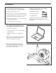
www.proform.com Model No. PFEL04910.1 Serial No. Write the serial number in the space above for reference. Serial Number Decal ACTIVATE YOUR WARRANTY To register your product and activate your warranty today, go to www.proformservice.com/ registration. CUSTOMER CARE For service at any time, go to www.proformservice.com. Or call 1-888-533-1333 Mon.–Fri. 6 a.m.–6 p.m. MT Sat. 8 a.m.–12 p.m. MT Please do not contact the store.
TABLE OF CONTENTS WARNING DECAL PLACEMENT . . . . . . . . . . . . . . . . . . . . . . . . . . . . . . . . . . . . . . . . . . . . . . . . . . . . . . . . . . . . . . . 2 IMPORTANT PRECAUTIONS . . . . . . . . . . . . . . . . . . . . . . . . . . . . . . . . . . . . . . . . . . . . . . . . . . . . . . . . . . . . . . . . . . 3 BEFORE YOU BEGIN. . . . . . . . . . . . . . . . . . . . . . . . . . . . . . . . . . . . . . . . . . . . . . . . . . . . . . . . . . . . . . . . . . . . . . . .
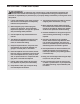
IMPORTANT PRECAUTIONS WARNING: To reduce the risk of serious injury, read all important precautions and instructions in this manual and all warnings on your elliptical before using your elliptical. ICON assumes no responsibility for personal injury or property damage sustained by or through the use of this product. 1. It is the responsibility of the owner to ensure that all users of the elliptical are adequately informed of all precautions. 9.
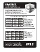
STANDARD SERVICE PLANS all 4
BEFORE YOU BEGIN Thank you for purchasing the PROFORM® 500 LE elliptical. The 500 LE elliptical provides an array of features designed to make your workouts at home more effective and enjoyable. manual. To help us assist you, note the product model number and serial number before contacting us. The model number and the location of the serial number decal are shown on the front cover of this manual. For your benefit, read this manual carefully before you use the elliptical.
PART IDENTIFICATION CHART Use the drawings below to identify the small parts needed for assembly. The number in parentheses below each drawing is the key number of the part, from the PART LIST near the end of this manual. The number following the key number is the quantity needed for assembly. Note: If a part is not in the hardware kit, check to see if it has been preassembled. Extra parts may be included.
ASSEMBLY • To hire an authorized service technician to assemble this product, call 1-800-445-2480. • In addition to the included tool(s), assembly requires the following tool(s): • Assembly requires two persons. one Phillips screwdriver • Place all parts in a cleared area and remove the packing materials. Do not dispose of the packing materials until you finish all assembly steps. one adjustable wrench • Left parts are marked “L” or “Left” and right parts are marked “R” or “Right.
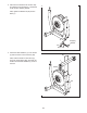
3. Remove the indicated screw and the shipping bracket from the Base (1). Discard the screw and the shipping bracket. 3 Next, tighten the Base Foot (26) into the Base (1). 1 Shipping Bracket 26 Screw 4. Attach the Rear Stabilizer (7) to the Frame (2) with two M10 x 127mm Screws (83). 4 83 Next, hold the handle on the Frame (2), press the Latch Button (68), and lower the Frame until the Rear Stabilizer (7) rests on the floor.
5. Hold a Hub Cover (75) and a Crank Arm (36) against the Crank (45). 5 Align the holes in the Hub Cover (75) and the Crank Arm (36) with the unused holes in the left side of the Crank (45). 43 Insert four Hub Screws (87) into the Hub Cover (75) and the Crank Arm (36), and finger tighten the Hub Screws into the Crank (45). Tighten one Hub Screw, and then tighten the Hub Screw across from the first Hub Screw. Then, tighten the remaining two Hub Screws.
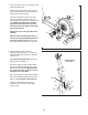
7. Identify the Left Upright Cover (17) and hold it against the left side of the Upright (3). 7 Attach the Left Upright Cover (17) with two M4 x 16mm Round Head Screws (101). 3 39 101 Attach the Right Upright Cover (39) in the same way. 17 101 8. Identify the Left and Right Handlebars (119, 120) and orient them as shown. 8 116 Tip: Avoid pinching the Pulse Wires (118). Attach the Left and Right Handlebars (119, 120) to the Upright (3) with two M8 x 80mm Bolts (116) and two M8 Jam Nuts (79).
9. Insert the Pulse Wires (118) upward through the Upright (3) as shown. 9 3 118 118 10. While a second person holds the Console (5) near the Upright (3), connect the wires on the Console to the Upper Wire Harness (48) and to the Pulse Wires (118). 10 5 Insert the excess wire into the Upright (3) or into the Console (5). 3 Tip: Avoid pinching the wires. Attach the Console (5) to the Upright (3) with four M4 x 16mm Round Head Screws (101). 101 118 48 Avoid pinching the wires 11.
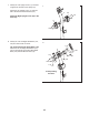
. Identify the Left Upper Body Arm (8) and the Left Upper Body Leg (11) and orient them as shown. 12 Insert the Left Upper Body Arm (8) into the Left Upper Body Leg (11). 9 Attach the Left Upper Body Arm (8) with two M8 x 41mm Bolts (78) and two M8 Jam Nuts (79). Make sure that the Jam Nuts are in the hexagonal holes in the Left Upper Body Leg (11). 8 79 Hexagonal Holes Attach the Right Upper Body Arm (9) to the Right Upper Body Leg (12) in the same way. 78 79 78 12 11 13.
14. Hold the Left Front Arm Cover (18) and the Left Rear Arm Cover (19) around the Left Upper Body Leg (11). 14 Attach the Arm Covers (18, 19) with three M4 x 32mm Round Head Screws (105). Attach the Right Front Arm Cover (20) and the Right Rear Arm Cover (21) in the same way. 20 105 21 12 18 19 11 15. Identify the Left Pedal (13) and the Left Pedal Arm (14).
16. Apply a small amount of grease to one of the Pedal Arm Axles (32). 16 Next, slide an M8 Washer (88) and a Pedal Arm Cover (31) onto an M8 x 23mm Shoulder Screw (115), and turn the Shoulder Screw a few turns into the Pedal Arm Axle (32). 11 While a second person holds the front end of the Left Pedal Arm (14) inside the bracket on the Left Upper Body Leg (11), insert the Pedal Arm Axle (32) into both parts.
18. See the upper drawing. Plug the Power Adapter (60) into the receptacle on the Console (5). 18 5 To plug the Power Adapter (60) into an outlet, see HOW TO PLUG IN THE POWER ADAPTER on page 16. See the lower drawing. Note: The Console (5) can also be operated with four D batteries (not included); alkaline batteries are recommended. Do not use old and new batteries together or alkaline, standard, and rechargeable batteries together.
HOW TO USE THE ELLIPTICAL HOW TO PLUG IN THE POWER ADAPTER IMPORTANT: If the elliptical has been exposed to cold temperatures, allow it to warm to room temperature before you plug in the power adapter. If you do not do this, you may damage the console displays or other electronic components. Plug the power adapter into the receptacle on the console. Then, plug the power adapter into an appropriate outlet that is properly installed in accordance with all local codes and ordinances.
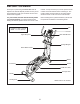
HOW TO EXERCISE ON THE ELLIPTICAL Note: The crank arms can turn in either direction. It is recommended that you turn the crank arms in the direction shown by the arrow; however, for variety, you can turn the crank arms in the opposite direction. To mount the elliptical, hold the upper body arms or the handlebars and step onto the pedal that is in the lowest position. Next, step onto the other pedal. Push the pedals until they begin to move with a continuous motion.
CONSOLE DIAGRAM FEATURES OF THE CONSOLE For example, lose unwanted pounds with the 8-week Weight Loss workout. iFit workouts control the resistance of the pedals while the voice of a personal trainer coaches you through your workouts. iFit cards are available separately. To purchase iFit cards, go to www.iFit.com or call the telephone number on the front cover of this manual. iFit cards are also available at select stores.
HOW TO USE THE MANUAL MODE 4. Follow your progress with the display. 1. Turn on the console. The left display—This display can show the elapsed time and the approximate number of calories you have burned. The display will change modes every few seconds. Press any button or begin pedaling to turn on the console. When you turn on the console, the display will turn on. A tone will sound and the console will be ready for use. Note: During a workout, the display will show the time remaining in the workout.
5. Measure your heart rate if desired. HOW TO USE A PRESET WORKOUT If there are sheets of plastic on the Contacts metal contacts on the handgrip heart rate monitor, remove the plastic. In addition, make sure that your hands are clean. To measure your heart rate, hold the handgrip heart rate monitor with your palms resting against the metal contacts. Avoid moving your hands or gripping the contacts tightly. 1. Turn on the console. See step 1 on page 19. 2. Select a preset workout.
At the end of each segment of the workout, a series of tones will sound and the next segment of the profile will begin to flash. If a different resistance level is programmed for the next segment, the resistance level will flash in the display for a few seconds to alert you. The resistance of the pedals will then change. HOW TO USE AN IFIT WORKOUT iFit cards are available separately. To purchase iFit cards, go to www.iFit.com or see the front cover of this manual.
HOW TO USE THE SOUND SYSTEM that the audio cable is fully plugged in. Note: To purchase an audio cable, see your local electronics store. To play music or audio books through the console sound system while you exercise, plug a 3.5 mm male to 3.5 mm male audio cable (not included) into the jack on the console and into a jack on your MP3 player, CD player, or other personal audio player; make sure Next, press the play button on your personal audio player.
EXERCISE GUIDELINES Burning Fat—To burn fat effectively, you must exercise at a low intensity level for a sustained period of time. During the first few minutes of exercise, your body uses carbohydrate calories for energy. Only after the first few minutes of exercise does your body begin to use stored fat calories for energy. If your goal is to burn fat, adjust the intensity of your exercise until your heart rate is near the lowest number in your training zone.
PART LIST Key No. Qty. 1 2 3 4 5 6 7 8 9 10 11 12 13 14 15 16 17 18 19 20 21 22 23 24 25 26 27 28 29 30 31 32 33 34 35 36 37 38 39 40 41 42 43 44 45 46 47 48 49 50 51 1 1 1 1 1 1 1 1 1 2 1 1 1 1 1 1 1 1 1 1 1 1 2 2 2 1 2 1 1 6 4 2 4 1 2 2 2 1 1 1 2 4 2 2 1 1 2 1 1 1 1 Model No. PFEL04910.1 R1213A Description Key No. Qty.
Key No. Qty. 103 104 105 106 107 108 109 110 111 112 113 24 8 6 2 4 2 2 2 2 8 1 Description Key No. Qty.
EXPLODED DRAWING A Model No. PFEL04910.
EXPLODED DRAWING B Model No. PFEL04910.
ORDERING REPLACEMENT PARTS To order replacement parts, please see the front cover of this manual.