Model No. PFEL13031 Serial No. USER’S MANUAL Serial Number Decal QUESTIONS? If you have questions, or if there are missing parts, we will guarantee complete satisfaction through direct assistance from our factory. TO AVOID DELAYS, PLEASE CALL DIRECT TO OUR TOLLFREE CUSTOMER HOT LINE. The trained technicians on our customer hot line will provide immediate assistance, free of charge to you. CUSTOMER HOT LINE: 1-888-533-1333 Mon.–Fri., 6 a.m.–6 p.m.
TABLE OF CONTENTS IMPORTANT PRECAUTIONS . . . . . . . . . . . . . . . . . . . . . . . . . . . . . . . . . . . . . . . . . . . . . . . . . . . . . . . . . . . . . . . .3 BEFORE YOU BEGIN . . . . . . . . . . . . . . . . . . . . . . . . . . . . . . . . . . . . . . . . . . . . . . . . . . . . . . . . . . . . . . . . . . . . . .4 ASSEMBLY . . . . . . . . . . . . . . . . . . . . . . . . . . . . . . . . . . . . . . . . . . . . . . . . . . . . . . . . . . . . . . . . . . . . . . . . . . . . . . .
IMPORTANT PRECAUTIONS WARNING: To reduce the risk of serious injury, read the following important precautions before using the elliptical exerciser. 1. Read all instructions in this manual before using the elliptical exerciser. 11. Keep your back straight when using the elliptical exerciser; do not arch your back. 2. It is the responsibility of the owner to ensure that all users of the elliptical exerciser are adequately informed of all precautions. 12.
BEFORE YOU BEGIN Thank you for selecting the new PROFORM® 1280 S elliptical exerciser. The PROFORM® 1280 S is an incredibly smooth exerciser that moves your feet in a natural elliptical path, minimizing the impact on your knees and ankles. And the unique 1280 S features adjustable resistance and a state-of-the-art console to help you get the most from your exercise. Welcome to a whole new world of natural, elliptical-motion exercise from PROFORM.
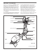
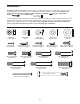
ASSEMBLY Assembly requires two persons. Place all parts of the elliptical exerciser in a cleared area and remove the packing materials. Do not dispose of the packing materials until assembly is completed. In addition to the , an adjustable included allen wrenches, assembly requires a phillips screwdriver wrench , and a rubber mallet . See the drawings below to identify the small parts needed for assembly.
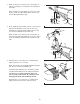
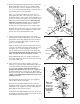
1. While another person lifts the front of the Frame (1), thread a Leveling Foot (72) fully into the underside of the Frame. 1 Next, attach the Front Stabilizer (3) to the front of the Frame (1) with two M8 x 54mm Button Screws (33) and two M8 Split Washers (94). 3 94 94 2. Move and lift the left Flex Bar (14) out of the way and slide the Left Stabilizer Cover (31) onto the Front Stabilizer (3). Slide the Right Stabilizer Cover (116) onto the Front Stabilizer in the same way.
4. Identify the Ramp Axle (128), which is the longest axle. Slide a Ramp Axle Cover (132) onto an M6 x 18mm Patch Screw (67) as shown. Tighten the Patch Screw into one end of the Ramp Axle. Apply a small amount of the included grease to the Ramp Axle. 4 133 Have a second person hold the two Ramp Spacers (130) against the sides of the Frame (1) so they cover the indicated tubes on the Frame. Lift the Flex Bars (not shown) out of the way and align the round tubes on the Ramp (133) with the Ramp Spacers.
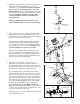
7. Identify the Left Handlebar (9), which is marked with a sticker. Insert the Left Handlebar into one of the Handlebar Legs (79); make sure that the Handlebar Leg is turned so the hexagonal holes are on the indicated side. Attach the Left Handlebar with two M8 x 43mm Button Bolts (50) and two M8 Nylon Locknuts (46). Do not tighten the Button Bolts yet. Make sure that the Nylon Locknuts are seated in the hexagonal holes.
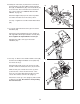
10. Identify the Left Pedal (13). Attach the Left Pedal to the left Flex Bar (14) with an M10 x 35mm Carriage Bolt (20), an M10 Washer (99), and a Pedal Knob (15) as shown. Note: The Left Pedal can be attached in any of five positions (see HOW TO ADJUST THE PEDALS on page 11). 10 20 12 Attach the Right Pedal (12) in the same way. Make sure that both Pedals are in the same position. 13 See step 7. Tighten the four M8 x 43mm Button Bolts (50). 99 15 11.
13. Attach the Left Handlebar Cover (109) to the Console (5) with three M4 x 16mm Screws (66). Attach the Right Handlebar Cover (110) in the same way. 13 5 See assembly step 11. Tighten the eight M6 x 16mm Tapered Button Screws (107). 110 109 66 66 14. Plug the Power Cord (96) into the Power Socket (140) at the rear of the elliptical exerciser. 14 96 140 15. Make sure that all parts of the elliptical exerciser are properly tightened. Note: Some hardware may be left over after assembly is completed.
HOW TO USE THE ELLIPTICAL EXERCISER HOW TO PLUG IN THE POWER CORD The green-colored rigid ear, lug, or the like extending from the adapter must be connected to a permanent ground such as a properly grounded outlet box cover. Whenever the adapter is used, it must be held in place by a metal screw. Some 2-pole receptacle outlet box covers are not grounded. Contact a qualified electrician to determine if the outlet box cover is grounded before using an adapter.
FEATURES OF THE CONSOLE The advanced console offers a selection of features designed to make your workouts more enjoyable and effective. When the manual mode of the console is selected, the resistance of the pedals and the angle of the ramp can be changed with the touch of a button. As you work out, the console will provide continuous exercise feedback. You can even measure your heart rate using the handgrip pulse sensor. The console also offers ten Smart programs.
To use the manual mode of the console, see the instructions below. To use a Smart program, see page 15. To use a Heart Rate program, see page 16. To use an iFIT.com CD program, see page 18. To use an iFIT.com video program, see page 20. To use a program directly from our Web site, see page 21. 4 The upper section of the large display will show the distance you have pedaled and the numbers of calories and fat calories you have burned (see FAT BURNING on page 23).
The small display will show your pedaling pace (in revolutions per minute). The indicator bar in the small display will Indicator Bar increase or decrease in length as you increase or decrease your pedaling pace. Note: When you use a Heart Rate program, the small display will show your heart rate instead of your pedaling pace. For the most accurate heart rate reading, continue to hold the handgrips for about 30 seconds.
your pace until one segment of Indicator the indicator bar Bar appears at the tip of each arrow Arrows (see the drawing at the right). Note: When the word TARGET does not appear in the small display, your actual pedaling pace will be shown. Important: The target pace is intended only to provide a goal. Your actual pace may be slower than the target pace, especially during the first few months of your exercise program. Make sure to pedal at a pace that is comfortable for you.
5 HOW TO USE A HEART RATE PROGRAM Heart rate program 1 consists of 20 one-minute periods. One resistance level and one target heart rate are programmed for each period. (Note: The same resistance level and/or target heart rate may be programmed for two or more consecutive periods.) Heart Rate program 2 is sixty minutes long (you may choose to use only part of the program). The same resistance level and target heart rate are programmed for the entire program.
The program will continue in this way until the large display shows that no time remains in the program. Note: If you stop pedaling for a few seconds, the program will end. To use the program again, reselect it and start it at the beginning. 6 7 Turn on the fan if desired. See step 6 on page 14. 8 When you are finished exercising, the console will automatically turn off. Follow your progress with the large display. See step 7 on page 14. See step 4 on page 13.
pace is about to change. Note: If the resistance level and/or the target pace does not change when a “chirp” is heard, make sure that the iFIT.com indicator is lit. In addition, adjust the volume (see step 5 below). If the volume is too high or too low, the console may not detect the program signals. HOW TO USE IFIT.COM CD PROGRAMS When you use an iFIT.
HOW TO CONNECT TO YOUR COMPUTER HOW TO CONNECT THE ELLIPTICAL EXERCISER TO YOUR VCR OR COMPUTER Note: If your computer has a 1/8” LINE OUT jack, see instruction A. If your computer has only a PHONES jack, see instruction B. HOW TO CONNECT TO YOUR VCR A. Plug one end of a 1/8” to 1/8” stereo audio cable (available at electronics stores) into the jack beneath the console. Plug the other end of the cable into the LINE OUT jack on your computer.
The video program will function in almost the same way as a Smart program (see step 3 on page 15). However, an electronic “chirping” sound will alert you when the resistance level and/or the target pace is about to change. HOW TO USE IFIT.COM VIDEO PROGRAMS To use iFIT.com videocassettes, the elliptical exerciser must be connected to your VCR. See HOW TO CONNECT TO YOUR VCR on page 19. To purchase iFIT.com videocassettes, call toll-free 1-888-5331333.
HOW TO USE PROGRAMS DIRECTLY FROM OUR WEB SITE Our Web site at www.iFIT.com allows you to play iFIT.com programs directly from the internet. To use programs from our Web site, the elliptical exerciser must be connected to your computer. See HOW TO CONNECT TO YOUR COMPUTER on page 19. In addition, you must have an internet connection and an internet service provider. A list of specific system requirements is found on our Web site. 5 Follow the desired links on our Web site to select a program.
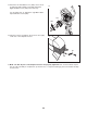
MAINTENANCE AND TROUBLESHOOTING HOW TO MOVE THE ELLIPTICAL EXERCISER Inspect and properly tighten all parts of the elliptical exerciser regularly. Replace any worn parts immediately. Stand in front of the elliptical exerciser, hold the handlebars firmly, and place one foot against the ramp in the location shown below. Pull the handlebars until the elliptical exerciser can be moved on the front wheels, and carefully move the elliptical exerciser to the desired location.
CONDITIONING GUIDELINES During the first few minutes of exercise, your body uses easily accessible carbohydrate calories for energy. Only after the first few minutes of exercise does your body begin to use stored fat calories for energy. If your goal is to burn fat, adjust the intensity of your exercise until your heart rate is near the lowest number in your training zone as you exercise. WARNING: • Before beginning this or any exercise program, consult your physician.
PART LIST—Model No. PFEL13031 Key No. Qty. 1 2 3 4 5 6 7 8 9 10 11 12 13 14 15 16 17 18 19 20 21 22 23 24 25 26 27 28 29 30 31 32 33 34 35 36 37 38 39 40 41 42 43 44 45 46 47 48 49 50 51 52 1 1 1 1 1 1 1 1 1 1 2 1 1 2 2 1 2 3 6 2 2 2 2 6 2 1 2 4 1 1 1 2 6 1 1 1 1 1 1 2 1 2 1 1 5 8 2 1 1 4 1 1 Description R0204A Key No. Qty.
Key No. Qty. 105 106 107 108 109 110 111 112 113 114 115 116 117 118 119 120 121 122 123 124 125 126 1 1 8 1 1 1 7 2 1 1 2 1 2 2 2 1 1 1 2 1 1 1 Description Key No. Qty.
117 50 53 22 24 23 9 28 119 79 57 46 24 34 24 66 143 118 94 26 2 94 70 107 66 66 25 66 93 71 107 107 107 63 24 94 94 91 33 66 118 45 46 57 24 93 29 25 38 71 50 108 143 119 117 79 24 66 6 66 23 10 28 53 84 22 7 11 84 111 74 84 111 84 111 66 66 68 109 8 111 66 110 18 111 84 114 80 5 EXPLODED DRAWING—Model No.
59 58 27 64 74 87 86 58 27 17 15 99 133 45 20 14 59 58 65 67 98 66 75 129 16 19 122 121 46 131 83 58 72 84 59 101 100 36 100 59 52 44 58 27 72 35 78 115 21 106 40 33 105 37 4 18 49 99 15 51 112 20 46 60 62 62 90 90 61 55 85 104 103 1 97 42 58 17 64 84 58 59 72 66 98 33 115 69 77 73 42 46 43 41 76 27 54 89 30 113 84 89 33 94 73 32 88 98 3 47 120 124 126 127 32 59 95 116 84 123 126 125 45 31 130 139 58 132 67 67 128 131 129 131
HOW TO ORDER REPLACEMENT PARTS To order replacement parts, simply call our Customer Service Department toll-free at 1-888-533-1333, Monday through Friday, 6 a.m. until 6 p.m. Mountain Time (excluding holidays).