www.proform.com Model No. PFEL55911.0 Serial No. Write the serial number in the space above for reference. Serial Number Decal (under frame) QUESTIONS? If you have questions, or if parts are damaged or missing, DO NOT CONTACT THE STORE; please contact Customer Care. IMPORTANT: Please register this product (see the limited warranty on the back cover of this manual) before contacting Customer Care. CALL TOLL-FREE: 1-888-533-1333 Mon.–Fri., 6 a.m.–6 p.m. MT Sat. 8 a.m.–4 p.m. MT ON THE WEB: www.
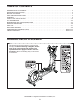
TABLE OF CONTENTS WARNING DECAL PLACEMENT . . . . . . . . . . . . . . . . . . . . . . . . . . . . . . . . . . . . . . . . . . . . . . . . . . . . . . . . . . . . . . . 2 IMPORTANT PRECAUTIONS . . . . . . . . . . . . . . . . . . . . . . . . . . . . . . . . . . . . . . . . . . . . . . . . . . . . . . . . . . . . . . . . . . 3 BEFORE YOU BEGIN. . . . . . . . . . . . . . . . . . . . . . . . . . . . . . . . . . . . . . . . . . . . . . . . . . . . . . . . . . . . . . . . . . . . . . . .
IMPORTANT PRECAUTIONS WARNING: To reduce the risk of serious injury, read all important precautions and instructions in this manual and all warnings on your elliptical before using your elliptical. ICON assumes no responsibility for personal injury or property damage sustained by or through the use of this product. 9. The elliptical should not be used by persons weighing more than 275 lbs. (125 kg). 1. Before beginning any exercise program, consult your physician.
BEFORE YOU BEGIN Thank you for selecting the revolutionary PROFORM® 10.0 CE elliptical. The 10.0 CE elliptical provides an impressive selection of features designed to make your workouts at home more effective and enjoyable. manual. To help us assist you, note the product model number and serial number before contacting us. The model number and the location of the serial number decal are shown on the front cover of this manual. For your benefit, read this manual carefully before you use the elliptical.
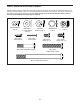
PART IDENTIFICATION CHART Use the drawings below to identify the small parts needed for assembly. The number in parentheses below each drawing is the key number of the part, from the PART LIST near the end of this manual. The number following the key number is the quantity needed for assembly. Note: If a part is not in the hardware kit, check to see if it has been preassembled. Extra parts may be included. M8 Split Washer (131)–6 M4 x 16mm Screw (93)–16 M8 x 23mm x 1.
ASSEMBLY • To hire an authorized service technician to assemble the elliptical, call 1-800-445-2480. • In addition to the included tool(s), assembly requires the following tools: • Assembly requires two persons. one Phillips screwdriver • Place all parts in a cleared area and remove the packing materials. Do not dispose of the packing materials until you complete all assembly steps. one rubber mallet Assembly may be easier if you have your own set of wrenches.
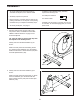
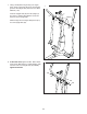
3. Orient the Small Bumper (13) so that the recessed holes are in the indicated location. 3 While a second person lifts the Frame (1), attach the Small Bumper (13) to the underside of the Frame with two M4 x 25mm Screws (132). 1 13 132 4. Identify and orient the Upright (5) and the Top Cover (23) as shown. Slide the Top Cover upward onto the Upright. 4 Have a second person hold the Upright (5) and the Top Cover (23) near the Frame (1). Connect the Upright Wire (60) to the Frame Wire (109).
5. Tip: Avoid pinching the wires. Insert the Upright (5) into the Frame (1). 5 Attach the Upright (5) with six M8 x 16mm Screws (102) and six M8 Split Washers (131). Do not tighten the Screws yet. Slide the Top Cover (23) downward. Do not press the Top Cover into the Right and Left Frame Covers (21, 22) yet. Avoid pinching the wires 23 5 102 1 102 131 131 21, 22 6. Identify the Right Upper Body Arm (8) and the Right Upper Body Leg (6), which are marked with “R” stickers, and orient them as shown.
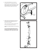
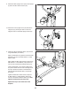
7. Using a small plastic bag to keep your fingers clean, apply a generous amount of the included grease to the Upright Axle (48) and to two Wave Washers (118). 7 Insert the Upright Axle (48) into the Upright (5) and center it. Slide a Wave Washer (118) onto each end of the Upright Axle. 5 9 Grease 118 Slide the Right and Left Upper Body Arms (8, 9) onto the Upright Axle (48). 8 48 118 8. At the same time, tighten an M8 x 16mm Screw (102) and an M8 x 23mm x 1.
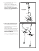
9. Attach the Rear Upright Cover (24) to the Upright (5) with four M4 x 16mm Screws (93). 9 93 5 24 10. Attach the Front Upright Cover (25) around the Upright (5) by pressing the tabs on the Front Upright Cover into the Rear Upright Cover (24). 10 25 5 24 11. Identify the Short Pedal Arm Axles (115) and the Long Pedal Axles (not shown). Apply a small amount of grease to a Short Pedal Arm Axle (115) and to an M8 x 23mm x 1.5mm Washer (126).
12. Identify the Right Pedal (14), which is marked with a “Right” sticker, and orient it as shown. 12 14 Attach the Right Pedal (14) to the right Pedal Arm (12) with three M8 x 50mm Button Screws (123). 12 Attach the Left Pedal (not shown) to the left Pedal Arm (12) in the same way. 12 123 13. Apply a small amount of grease to a Long Pedal Arm Axle (106) and to an M8 x 23mm x 1.5mm Washer (126). 13 Next, tighten an M8 x 16mm Screw (102) and an M8 x 23mm x 1.
15. Remove and discard the cap (not shown) on the right Adjustment Pin (44). 15 Attach an Adjustment Knob (45) to the right Adjustment Pin (44) with an M6 x 12mm Screw (111). 45 Then, press the tabs on a Knob Cap (46) into the Adjustment Knob (45). 111 44 46 Repeat this step on the other side of the elliptical. 16. See step 6. Tighten the six M8 x 45mm Button Bolts (104). 16 See step 5. Tighten the six M8 x 16mm Screws (102).
17. Orient the Console Cover (11) as shown. While a second person holds the Console Cover near the Upright (5), insert the Upright Wire (60) upward through the Console Cover. 17 11 Then, slide the Console Cover (11) onto the Upright (5). 60 5 18. Orient the Handlebar (10) as shown. Have a second person hold the Handlebar near the Upright (5). 18 10 Locate the Pulse Wires (135) in the Handlebar (10). Insert the Pulse Wires into the hole in the front of the Upright (5).
20. While a second person holds the Console (33) near the Handlebar (10), connect the console wires to the Upright Wire (60) and to the Pulse Wire (135). 20 33 Avoid pinching the wires Insert the excess wire into the Console (33) or into the Handlebar (10). 135 10 Tip: Avoid pinching the wires. Attach the Console (33) to the Handlebar (10) with four M4 x 16mm Screws (93). 60 93 21. Attach the Console Cover (11) to the Console (33) with two M4 x 16mm Screws (93). 21 33 93 11 22.
HOW TO USE THE ELLIPTICAL HOW TO PLUG IN THE POWER ADAPTER HOW TO MOVE THE ELLIPTICAL IMPORTANT: If the elliptical has been exposed to cold temperatures, allow it to warm to room temperature before you plug in the power adapter. If you do not do this, you may damage the console displays or other electronic components. To move the elliptical, first fold it as described at the left. Next, stand in front of the elliptical, hold the upright, and place one foot against one of the wheels.
HOW TO ADJUST THE STRIDE LENGTH HOW TO EXERCISE ON THE ELLIPTICAL To adjust the stride length of the elliptical, first loosen an adjustment knob. Next, pull the adjustment knob outward until the adjustment bracket will move freely. To mount the elliptical, hold the upper body arms or the handlebars and step onto the pedal that is in the lowest position. Next, step onto the other pedal. Push the pedals until they begin to move with a continuous motion. Note: The crank arms can turn in either direction.
CONSOLE DIAGRAM FEATURES OF THE CONSOLE The advanced console offers an array of features designed to make your workouts more effective and enjoyable. When you use the manual mode of the console, you can change the resistance of the pedals with the touch of a button. While you exercise, the console will display continuous exercise feedback. You can also measure your heart rate using the handgrip heart rate monitor.
HOW TO USE THE MANUAL MODE Distance (Dist.)—This display mode will show the distance that you have pedaled in miles or kilometers. 1. Begin pedaling or press any button on the console to turn on the console. Pulse—This display mode will show your heart rate when you use the handgrip heart rate monitor (see step 5 on page 19). When you turn on the console, the display will light. The console will then be ready for use. 2. Select the manual mode. Resistance (Resist.
Press the Home button to return to the default menu (see HOW TO CHANGE CONSOLE SETTINGS on page 22 to set the default menu). If necessary, press the Home button again. When your pulse is detected, a heart symbol in the calorie display will flash each time your heart beats, one or two dashes will appear, and then your heart rate will be shown. For the most accurate heart rate reading, hold the contacts for at least 15 seconds.
HOW TO USE AN ONBOARD WORKOUT As you exercise, you will be prompted to keep your pedaling speed near the target speed for the current segment. When an upward-pointing arrow appears in the display, increase your pace. When a downward-pointing arrow appears, decrease your pace. When no arrow appears, maintain your current pace. 1. Begin pedaling or press any button on the console to turn on the console. When you turn on the console, the display will light. The console will then be ready for use. 2.
HOW TO USE AN IFIT LIVE WORKOUT 5. Start the workout. 1. Begin pedaling or press any button on the console to turn on the console. See step 3 on page 20. During some workouts, the voice of a personal trainer will guide you through your workout. You can select an audio setting for your personal trainer (see HOW TO CHANGE CONSOLE SETTINGS on page 22). When you turn on the console, the display will light. The console will then be ready for use. 2. Insert the iFit Live module into the console.
HOW TO USE THE SOUND SYSTEM 5. Determine if an iFit Live module is connected to the console. To play music or audio books through the console sound system while you exercise, plug the included audio cable into the jack on the console and into a jack on your MP3 player or CD player; make sure that the audio cable is fully plugged in. If an iFit Live module is connected to the console, the display will show the words WIFI MODULE or USB MODULE.
FCC INFORMATION This equipment has been tested and found to comply with the limits for a Class B digital device, pursuant to part 15 of the FCC Rules. These limits are designed to provide reasonable protection against harmful interference in a residential installation. This equipment generates, uses, and can radiate radio frequency energy and, if not installed and used in accordance with the instructions, may cause harmful interference to radio communications.
MAINTENANCE AND TROUBLESHOOTING Inspect and tighten all parts of the elliptical regularly. Replace any worn parts immediately. Next, locate the Reed Switch (69). Loosen, but do not remove, the M4 x 16mm Screw (93). To clean the elliptical, use a damp cloth and a small amount of mild soap. IMPORTANT: To avoid damage to the console, keep liquids away from the console and keep the console out of direct sunlight.
HOW TO ADJUST THE DRIVE BELT If you can feel the pedals slip while you are pedaling, even when the resistance is adjusted to the highest level, the drive belt may need to be adjusted. Next, remove the M4 x 16mm Round Head Screws (127) and the M4 x 42mm Screws (124) from the Right and Left Shields (18, 19). Make sure to note which size of Screw you remove from each hole. Then, gently remove the Left Shield.
EXERCISE GUIDELINES Burning Fat—To burn fat effectively, you must exercise at a low intensity level for a sustained period of time. During the first few minutes of exercise, your body uses carbohydrate calories for energy. Only after the first few minutes of exercise does your body begin to use stored fat calories for energy. If your goal is to burn fat, adjust the intensity of your exercise until your heart rate is near the lowest number in your training zone.
PART LIST Key No. Qty. 1 2 3 4 5 6 7 8 9 10 11 12 13 14 15 16 17 18 19 20 21 22 23 24 25 26 27 28 29 30 31 32 33 34 35 36 37 38 39 40 41 42 43 44 45 46 47 48 49 50 1 1 1 1 1 1 1 1 1 1 1 2 1 1 1 2 2 1 1 1 1 1 1 1 1 1 1 1 1 1 1 1 1 2 2 2 2 1 2 8 4 1 2 2 2 2 4 1 1 1 Model No. PFEL55911.0 R0911A Description Key No. Qty.
Key No. Qty. 101 102 103 104 105 106 107 108 109 110 111 112 113 114 115 116 117 118 119 1 20 1 8 8 2 2 2 1 2 10 1 2 2 2 2 4 2 4 Description Key No. Qty. 120 121 122 123 124 125 126 127 128 129 130 131 132 133 134 135 136 * * Anchored Zip Tie M8 x 16mm Screw Left Wheel Lower Cover M8 x 45mm Button Bolt M8 Locknut Long Pedal Arm Axle M10 x 25mm Screw M10 x 32mm Washer Frame Wire M8 x 23.
124 127 19 127 124 59 20 102 33 18 10 34 127 93 24 26 124 93 93 34 124 93 57 11 5 93 135 93 57 23 93 93 22 25 93 93 132 21 93 EXPLODED DRAWING A Model No. PFEL55911.
39 40 40 120 17 30 128 100 120 72 16 38 93 128 54 37 73 41 93 75 41 4 75 86 99 74 97 41 93 95 69 70 93 54 133 37 85 77 82 93 2 79 129 98 101 96 76 93 87 86 112 90 91 80 94 67 93 93 84 42 68 41 102 110 66 108 130 64 125 127 64 63 107 13 132 127 58 127 108 3 105 128 60 103 36 110 102 76 122 71 87 65 88 109 83 89 127 104 56 78 94 107 92 81 61 1 120 40 16 104 105 55 100 102 17 40 39 136 36 120 131 102 102 1
57 93 31 134 47 113 111 45 31 126 46 102 9 93 47 43 52 102 53 117 115 121 114 53 43 121 113 102 44 126 111 116 12 117 62 32 44 118 126 57 93 35 111 47 123 47 15 51 126 102 111 134 45 62 46 117 116 114 126 115 106 126 117 102 119 119 50 104 123 111 102 49 7 123 102 12 126 93 118 35 14 102 48 111 29 126 93 105 119 27 6 105 105 93 57 93 106 30 102 126 28 104 57 126 102 8 EXPLODED DRAWING C Model No. PFEL55911.
ORDERING REPLACEMENT PARTS To order replacement parts, please see the front cover of this manual.