www.proform.com Model No. PFEL55914.0 Serial No. Write the serial number in the space above for reference. Serial Number Decal ACTIVATE YOUR WARRANTY To register your product and activate your warranty today, go to www.proformservice.com/ registration. CUSTOMER CARE For service at any time, go to www.proformservice.com. Or call 1-888-533-1333 Mon.–Fri. 6 a.m.–6 p.m. MT Sat. 8 a.m.–12 p.m. MT Please do not contact the store.
TABLE OF CONTENTS WARNING DECAL PLACEMENT . . . . . . . . . . . . . . . . . . . . . . . . . . . . . . . . . . . . . . . . . . . . . . . . . . . . . . . . . . . . . . .2 IMPORTANT PRECAUTIONS . . . . . . . . . . . . . . . . . . . . . . . . . . . . . . . . . . . . . . . . . . . . . . . . . . . . . . . . . . . . . . . . . . 3 BEFORE YOU BEGIN. . . . . . . . . . . . . . . . . . . . . . . . . . . . . . . . . . . . . . . . . . . . . . . . . . . . . . . . . . . . . . . . . . . . . . . .
IMPORTANT PRECAUTIONS WARNING: To reduce the risk of serious injury, read all important precautions and instructions in this manual and all warnings on your elliptical before using your elliptical. ICON assumes no responsibility for personal injury or property damage sustained by or through the use of this product. 1. It is the responsibility of the owner to ensure that all users of the elliptical are adequately informed of all precautions. 9.
STANDARD SERVICE PLANS all 5
BEFORE YOU BEGIN Thank you for selecting the revolutionary PROFORM® ENDURANCE 520 E elliptical. The ENDURANCE 520 E elliptical provides an impressive selection of features designed to make your workouts at home more effective and enjoyable. reading this manual, please see the front cover of this manual. To help us assist you, note the product model number and serial number before contacting us. The model number and the location of the serial number decal are shown on the front cover of this manual.
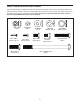
PART IDENTIFICATION CHART Use the drawings below to identify the small parts needed for assembly. The number in parentheses below each drawing is the key number of the part, from the PART LIST near the end of this manual. The number following the key number is the quantity needed for assembly. Note: If a part is not in the hardware kit, check to see if it has been preassembled. Extra parts may be included.
ASSEMBLY • To hire an authorized service technician to assemble this product, call 1-800-445-2480. • To identify small parts, see page 7. • In addition to the included tool(s), assembly requires the following tools: • Assembly requires two persons. • Place all parts in a cleared area and remove the packing materials. Do not dispose of the packing materials until you finish all assembly steps. one Phillips screwdriver • Left parts are marked “L” or “Left” and right parts are marked “R” or “Right.
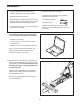
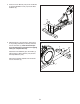
3. Press the Cover Mounts (106) on the underside of the Rear Stabilizer Cover (15) into the Rear Stabilizer (2). 3 15 106 2 4. With the help of a second person, place some of the packing materials (not shown) under the front of the Frame (1). Have the second person hold the Frame to prevent it from tipping while you complete this step. 4 6 105 Attach the Front Stabilizer (6) to the Frame (1) with two M10 x 122mm Screws (104) and two M10 Split Washers (105).
5. Orient the Upright (4) as shown. Have a second person hold the Upright near the Frame (1). 5 Wire Tie See the inset drawing. Locate the wire tie in the lower end of the Upright (4). Tie the wire tie to the Upper Wire (110). Then, pull the upper end of the wire tie until the Upper Wire is routed through the Upright. 110 110 Tip: To prevent the Upper Wire (110) from falling into the Upright (4), secure the Upper Wire with the wire tie. 4 Wire Tie 6. Tip: Avoid pinching the Upper Wire (110).
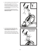
7. Using a plastic bag to keep your fingers clean, apply some of the included grease to the Pivot Axle (35) and to two 16mm Wave Washers (54). 7 Insert the Pivot Axle (35) through the Upright (4) and center it. Tip: It may be helpful to use a rubber mallet. 4 Identify the Right Upper Body Leg (60) and orient it as shown. 35 54 46 Slide a 16mm Wave Washer (54) and the Right Upper Body Leg (60) onto the right side of the Pivot Axle (35).
9. Untie and discard the wire tie on the Upper Wire (110). 9 7 While a second person holds the Console (7) near the Upright (4), connect the wires on the Console to the Upper Wire (110) and to the Pulse Sensor Wires (63). 63 Insert the excess wire into the Upright (4) or into the Console (7). 110 4 10. Tip: Avoid pinching the wires. Attach the Console (7) to the Upright (4) with four M4 x 16mm Screws (101); start all of the Screws, and then tighten them.
11. Orient the Right Pedal Arm (58) as shown. 11 Apply grease to the axle on the Right Pedal Arm (58). Attach the Right Pedal Arm (58) to the Right Roller Arm (59) with an M8 x 14mm Shoulder Screw (120), a Small Axle Cover (55), and an M8 Washer (97). Repeat this step for the Left Pedal Arm (44). 44 120 55 59 97 58 Grease 12. Apply a small amount of grease to one of the Pedal Arm Axles (64).
13. Orient the Rear Upright Cover (81) as shown. 13 Attach the Rear Upright Cover (81) to the Upright (4) with four M4 x 16mm Screws (101); start all of the Screws, and then tighten them. 117 Orient the Front Upright Cover (117) as shown. Attach the Front Upright Cover (117) around the Upright (4) by pressing the hooks on the Rear Upright Cover (81) onto the tabs on the Front Upright Cover. 101 81 14. Identify the Right Upper Body Arm Front Cover (65) and orient it as shown.
. Identify the Right Upper Body Leg Inner Cover (83) and orient it as shown. 15 Attach the Right Upper Body Leg Inner Cover (83) to the Right Upper Body Leg (60) with an M4 x 16mm Screw (101) and an M5 Washer (32). Identify the Right Upper Body Leg Outer Cover (69) and orient it as shown. 60 Attach the Right Upper Body Leg Outer Cover (69) around the Right Upper Body Leg (60) by pressing the hooks on the Right Upper Body Leg Inner Cover (83) onto the tabs on the Right Upper Leg Outer Cover.
17. Orient the Rear Console Cover (80) as shown. 17 79 Attach the Rear Console Cover (80) to the Upright (4) with two M4 x 16mm Screws (101). Orient the Front Console Cover (79) as shown. 101 Attach the Front Console Cover (79) around the Upright (4) by pressing the hooks on the Rear Console Cover (80) onto the tabs on the Front Console Cover. 4 80 18.
19. Plug the Power Adapter (119) into the receptacle on the frame of the elliptical. 19 119 Note: To plug the Power Adapter (119) into an outlet, see HOW TO PLUG IN THE POWER ADAPTER on page 18. 20. Make sure that all parts are properly tightened before you use the elliptical. Note: Extra parts may be included. Place a mat beneath the elliptical to protect the floor.
HOW TO USE THE ELLIPTICAL HOW TO PLUG IN THE POWER ADAPTER HOW TO LEVEL THE ELLIPTICAL IMPORTANT: If the elliptical has been exposed to cold temperatures, allow it to warm to room temperature before you plug in the power adapter. If you do not do this, you may damage the console displays or other electronic components. If the elliptical rocks slightly on your floor during use, turn one or both of the leveling feet beneath the rear of the frame until the rocking motion is eliminated.
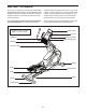
HOW TO CHANGE THE INCLINE OF THE RAMP To vary the motion of the pedals, you can change the incline of the ramp. To raise the ramp, simply pull the ramp handle upward to the desired incline level. Upper Body Arms Handlebars Ramp Handle Latch Button Pedals Ramp To lower the ramp, press the latch button, pull the ramp handle, and lower the ramp to the desired incline level. Then, release the latch button and engage the latch pin into one of the adjustment holes in the frame.
CONSOLE DIAGRAM MAKE YOUR FITNESS GOALS A REALITY WITH IFIT.COM Upload your workout results to the iFit cloud and track your accomplishments. With your new iFit-compatible fitness equipment, you can use an array of features on iFit.com to make your fitness goals a reality: Set calorie, time, or distance goals for your workouts. Exercise anywhere in the world with customizable Google Maps. Choose and download sets of weight-loss workouts.
FEATURES OF THE CONSOLE HOW TO USE THE MANUAL MODE The advanced console offers an array of features designed to make your workouts more effective and enjoyable. 1. Begin pedaling or press any button on the console to turn on the console. When you turn on the console, the display will turn on. The console will then be ready for use. When you use the manual mode, you can change the resistance of the pedals with the touch of a button.
Calories (Cals.)—This display mode will show the approximate number of calories you have burned. As you exercise, the workout intensity level bar will indicate the approximate intensity level of your exercise. Calories per Hour (Cals./Hr)—This display mode will show the approximate number of calories you are burning per hour. Distance (Dist.)—This display mode will show the distance that you have pedaled in miles or kilometers.
When your pulse is detected, a heart symbol will flash in the display each time your heart beats, one or two dashes will appear, and then your heart rate will be shown. For the most accurate heart rate reading, hold the contacts for at least 15 seconds. 6. When you are finished exercising, the console will turn off automatically. If the display does not show your heart rate, make sure that your hands are positioned as described.
HOW TO USE AN ONBOARD WORKOUT the profile will begin to flash. If a different resistance level and/or target rpm is programmed for the next segment, the resistance level and/or target rpm will appear in the display for a few seconds to alert you. The resistance of the pedals will then change. 1. Begin pedaling or press any button on the console to turn on the console. When you turn on the console, the display will turn on. The console will then be ready for use.
HOW TO USE A SET-A-GOAL WORKOUT Note: The calorie goal is an estimate of the number of calories that you will burn during the workout. The actual number of calories that you burn will depend on various factors such as your weight. In addition, if you manually change the resistance level during the workout, the number of calories you burn will be affected. 1. Begin pedaling or press any button on the console to turn on the console. When you turn on the console, the display will turn on.
HOW TO USE AN IFIT WORKOUT Press the Map button, the Train button, or the Lose Wt. button to download the next workout of that type in your schedule. You must have an iFit module to use an iFit workout. To purchase an iFit module at any time, go to www.iFit.com or call the telephone number on the front cover of this manual. Press the Compete button to compete in a race that you have previously scheduled.
6. Follow your progress with the display. HOW TO USE THE SOUND SYSTEM See step 4 on page 21. To play music or audio books through the console sound system while you exercise, plug a 3.5 mm male to 3.5 mm male audio cable (not included) into the jack on the console and into a jack on your MP3 player, CD player, or other personal audio player; make sure that the audio cable is fully plugged in. Note: To purchase an audio cable, see your local electronics store.
HOW TO CHANGE CONSOLE SETTINGS To view distance in miles, select ENGLISH. To view distance in kilometers, select METRIC. 1. Select the settings mode. Demo—The console features a display demo mode, designed to be used if the elliptical is displayed in a store. Press the Enter button repeatedly to turn the demo mode ON or OFF. To select the settings mode, press the gear button. The settings information will appear in the display.
FCC INFORMATION This equipment has been tested and found to comply with the limits for a Class B digital device, pursuant to part 15 of the FCC Rules. These limits are designed to provide reasonable protection against harmful interference in a residential installation. This equipment generates, uses, and can radiate radio frequency energy and, if not installed and used in accordance with the instructions, may cause harmful interference to radio communications.
MAINTENANCE AND TROUBLESHOOTING MAINTENANCE Note: For clarity, the left shield is shown removed in the drawing below. Inspect and tighten all parts of the elliptical regularly. Replace any worn parts immediately. Next, locate the Reed Switch (38). Turn the Pulley (19) until a Magnet (43) is aligned with the Reed Switch. To clean the elliptical, use a damp cloth and a small amount of mild soap.
HOW TO ADJUST THE DRIVE BELT See EXPLODED DRAWING C on page 39. Remove the M4 x 19mm Screws (5) and the M4 x 48mm Screw (107) from the Left and Right Shields (73, 74). Then, remove the Right Shield. If the pedals slip while you are pedaling, even while the resistance is adjusted to the highest level, the drive belt may need to be adjusted. Next, locate and loosen the Idler Screw (89). Next, tighten the Belt Adjustment Screw (91) until the Drive Belt (113) is tight. Then, retighten the Idler Screw.
EXERCISE GUIDELINES Burning Fat—To burn fat effectively, you must exercise at a low intensity level for a sustained period of time. During the first few minutes of exercise, your body uses carbohydrate calories for energy. Only after the first few minutes of exercise does your body begin to use stored fat calories for energy. If your goal is to burn fat, adjust the intensity of your exercise until your heart rate is near the lowest number in your training zone.
SUGGESTED STRETCHES The correct form for several basic stretches is shown at the right. Move slowly as you stretch; never bounce. 1. Toe Touch Stretch Stand with your knees bent slightly and slowly bend forward from your hips. Allow your back and shoulders to relax as you reach down toward your toes as far as possible. Hold for 15 counts, then relax. Repeat 3 times. Stretches: Hamstrings, back of knees and back. 1 2. Hamstring Stretch Sit with one leg extended.
NOTES 34
PART LIST Key No. Qty. 1 2 3 4 5 6 7 8 9 10 11 12 13 14 15 16 17 18 19 20 21 22 23 24 25 26 27 28 29 30 31 32 33 34 35 36 37 38 39 40 41 42 43 44 45 46 47 48 49 50 1 1 1 1 8 1 1 1 1 1 1 1 1 1 1 2 1 1 1 2 4 1 3 1 1 4 2 1 1 4 2 2 2 2 1 2 1 1 1 2 2 1 2 1 1 1 1 1 2 6 Model No. PFEL55914.0 R1014A Description Key No. Qty.
Key No. Qty. 101 102 103 104 105 106 107 108 109 110 111 112 113 38 10 8 4 8 3 1 2 2 1 1 3 1 Description Key No. Qty.
33 101 50 21 30 50 114 3 21 104 50 16 114 94 33 30 50 84 101 41 13 78 38 31 24 101 29 22 112 23 27 85 86 17 102 20 90 115 108 94 115 21 12 14 101 48 11 101 2 50 21 31 27 106 15 105 10 28 1 101 40 41 42 26 91 88 102 39 43 99 109 25 82 112 23 101 89 93 40 30 43 113 19 6 34 86 112 26 105 18 85 26 20 23 101 90 30 108 78 109 34 104 EXPLODED DRAWING A Model No. PFEL55914.
103 52 95 76 47 103 49 96 62 95 70 102 82 53 44 101 97 97 64 101 56 77 32 51 100 46 101 57 68 82 98 56 45 72 97 57 55 120 97 55 53 82 51 97 57 95 77 97 98 120 100 67 52 53 56 103 57 95 56 59 49 103 66 100 57 53 95 83 82 101 60 97 57 62 97 58 77 97 95 87 100 65 101 57 82 61 77 32 101 57 64 69 96 82 97 102 EXPLODED DRAWING B Model No. PFEL55914.
71 101 7 101 101 5 5 101 116 63 107 5 37 122 121 101 81 8 5 5 80 54 36 73 102 96 75 105 92 4 101 79 5 101 92 101 5 36 105 74 54 117 39 5 35 118 111 110 116 102 101 96 63 101 9 101 119 101 71 EXPLODED DRAWING C Model No. PFEL55914.
ORDERING REPLACEMENT PARTS To order replacement parts, please see the front cover of this manual.