proform.com Model No. PFEL59718.0 Serial No. Write the serial number in the space above for reference. Serial Number Decal ACTIVATE YOUR WARRANTY To register your product and activate your warranty today, go to my.proform.com. CUSTOMER CARE For service at any time, go to proformservice.com. Or call 1-888-533-1333 Mon.–Fri. 6 a.m.–6 p.m. MT Sat. 8 a.m.–12 p.m. MT Please do not contact the store. CAUTION Read all precautions and instructions in this manual before using this equipment.
TABLE OF CONTENTS WARNING DECAL PLACEMENT . . . . . . . . . . . . . . . . . . . . . . . . . . . . . . . . . . . . . . . . . . . . . . . . . . . . . . . . . . . . . . .2 IMPORTANT PRECAUTIONS. . . . . . . . . . . . . . . . . . . . . . . . . . . . . . . . . . . . . . . . . . . . . . . . . . . . . . . . . . . . . . . . . . 3 BEFORE YOU BEGIN. . . . . . . . . . . . . . . . . . . . . . . . . . . . . . . . . . . . . . . . . . . . . . . . . . . . . . . . . . . . . . . . . . . . . . . .6 PART IDENTIFICATION CHART.
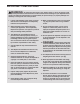
IMPORTANT PRECAUTIONS WARNING: To reduce the risk of burns, fire, electric shock, or injury to persons, read all important precautions and instructions in this manual and all warnings on your elliptical before using your elliptical. ICON assumes no responsibility for personal injury or property damage sustained by or through the use of this product. 1. It is the responsibility of the owner to ensure that all users of the elliptical are adequately informed of all precautions. 10.
1. The elliptical does not have a freewheel; the pedals will continue to move until the flywheel stops. Reduce your pedaling speed in a controlled way. 3. Over exercising may result in serious injury or death. If you feel faint, if you become short of breath, or if you experience pain while exercising, stop immediately and cool down. 2. Keep your back straight while using the elliptical; do not arch your back.
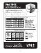
STANDARD SERVICE PLANS all 5
BEFORE YOU BEGIN Thank you for selecting the revolutionary PROFORM® COACHLINK E9.0 elliptical. The COACHLINK E9.0 elliptical provides an impressive selection of features designed to make your workouts at home more effective and enjoyable. reading this manual, please see the front cover of this manual. To help us assist you, note the product model number and serial number before contacting us. The model number and the location of the serial number decal are shown on the front cover of this manual.
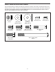
PART IDENTIFICATION CHART Use the drawings below to identify the small parts needed for assembly. The number in parentheses below each drawing is the key number of the part, from the PART LIST near the end of this manual. The number following the key number is the quantity needed for assembly. Note: If a part is not in the hardware kit, check to see if it has been preassembled. Extra parts may be included.
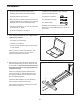
ASSEMBLY • To hire an authorized service technician to assemble this product, call 1-800-445-2480. • In addition to the included tool(s), assembly requires the following tools: • Assembly requires two persons. one Phillips screwdriver • Place all parts in a cleared area and remove the packing materials. Do not dispose of the packing materials until you finish all assembly steps. two adjustable wrenches • Left parts are marked “L” or “Left” and right parts are marked “R” or “Right.
3. With the help of a second person, place some of the packing materials (not shown) under the front of the Frame (1). Have the second person hold the Frame to prevent it from tipping while you complete this step. 3 104 6 If there are shipping supports attached to the front of the Frame (1), remove the screws from the shipping supports, and discard the screws and the shipping supports. Attach the Front Stabilizer (6) to the Frame (1) with two M10 x 114mm Screws (104).
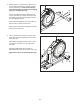
5. Tip: Avoid pinching the Upper Wire (110). Have a second person hold the Upright (4) on the Frame (1). 5 Avoid pinching the Upper Wire (110) Tip: Two M10 x 25mm Screws (92) are preattached to the Frame (1). 92 Attach the Upright (4) to the Frame (1) with two additional M10 x 25mm Screws (92); do not fully tighten the Screws yet. 4 110 92 1 6. Locate the wire tie (A) in the lower end of the Upright (4). See the inset drawing. Tie the wire tie to the Upper Wire (110) as shown in the inset drawing.
7. Apply grease to the axle on the right side of the Upright (4). 7 Next, slide a Pivot Spacer (54) onto the right side of the Upright (4). 4 Grease 54 Then, identify the Right Upper Body Leg (60), orient it as shown, and slide it onto the right side of the Upright (4). 46 Attach the Right Upper Body Leg (60) with an M8 x 13mm Screw (82) and an M8 x 28mm Washer (97). 60 97 82 Repeat this step for the Left Upper Body Leg (46). 8.
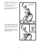
9. Apply grease to a Pedal Arm Axle (64). 9 Insert the Pedal Arm Axle (64) into the Right Upper Body Leg (60) and the Right Pedal Arm (58) from the direction shown. Next, slide an M8 x 22mm Washer (129) onto an M8 x 13mm Screw (82), and tighten the Screw a few turns into the Pedal Arm Axle (64). Then, tighten the Pedal Arm Axle (64) and the M8 x 13mm Screw (82) at the same time. 82 60 129 64 Repeat this step on the other side of the elliptical. Grease 58 10. See step 5.
11. Orient the Rear Console Cover (80) as shown, and attach it to the Upright (4) with two M4 x 16mm Screws (101). 11 79 101 Then, orient the Front Console Cover (79) as shown, and attach it to the Rear Console Cover (80) with two M4 x 16mm Screws (101). 101 101 4 80 12. Orient the Accessory Tray (37) as shown, and attach it to the Upright (4) with two M4 x 16mm Screws (101). 12 4 37 13.
. Identify the Right Upper Body Arm (61), orient it as shown, and insert it into the Right Upper Body Leg (60). 14 Attach the Right Upper Body Arm (61) with two M8 x 45mm Bolts (96) and two M8 Locknuts (102); make sure that the Locknuts are in the hexagonal holes (C). 96 47 Repeat this step for the Left Upper Body Arm (47). 60 61 102 15. Orient the Front Shield Cover (117) and the Center Shield Cover (75) around the Upright (4). Then, attach them to each other with two M4 x 16mm Screws (101).
17. Orient the Right Arm Front and Rear Covers (65, 66) around the Right Upper Body Leg (60) as shown, and then attach them with two M4 x 16mm Screws (101). 17 Repeat this step on the other side of the elliptical. 65 101 60 66 18. Attach the Tablet Holder (132) to the Console (7) with four Tablet Holder Screws (133); start all the Tablet Holder Screws, and then tighten them. 18 7 132 133 Make sure that all parts are properly tightened. Place a mat beneath the elliptical to protect the floor.
HOW TO USE THE ELLIPTICAL HOW TO PLUG IN THE POWER CORD A temporary adapter may be used to connect the power cord to a 2-pole receptacle as shown at the right if a properly grounded outlet is not available. This product must be grounded. If it should malfunction or break down, grounding provides a path of least resistance for electric current to reduce the risk of electric shock. The power cord has a plug with a grounding pin.
HOW TO MOVE THE ELLIPTICAL HOW TO LEVEL THE ELLIPTICAL Due to the size and weight of the elliptical, moving it requires two persons. Stand in front of the elliptical, hold the upright (A), and place one foot against one of the wheels (B). Pull on the upright and have a second person lift the handle (C) until the elliptical will roll on the wheels. Carefully move the elliptical to the desired location, and then lower it to the floor.
HOW TO EXERCISE ON THE ELLIPTICAL H To mount the elliptical, hold the handlebars (G) or the upper body arms (H) and step onto the pedal (I) that is in the lower position. Then, step onto the other pedal. Push the pedals until they begin to move with a continuous motion. Note: The pedals can turn in either direction. It is recommended that you turn the pedals in the direction shown by the arrow; however, for variety, you can turn the pedals in the opposite direction.
CONSOLE DIAGRAM FEATURES OF THE CONSOLE IMPORTANT: To activate your console and begin using its exclusive features, see assembly step 19 on page 15. The console also offers a selection of onboard workouts. Each onboard workout automatically changes the resistance of the pedals and prompts you to maintain a target pedaling speed as it guides you through an effective workout. The advanced console offers an array of features designed to make your workouts more effective and enjoyable.
HOW TO TURN ON THE POWER HOW TO USE THE MANUAL MODE IMPORTANT: If the elliptical has been exposed to cold temperatures, allow it to warm to room temperature before you turn on the power. If you do not do this, you may damage the console or other electrical components. 1. Begin pedaling or press any button on the console to turn on the console. Plug in the power cord (see HOW TO PLUG IN THE POWER CORD on page 14). Next, locate the power switch on the frame near the power cord.
Calories per Hour (CALS/HR)—The approximate number of calories you are burning per hour. To manually advance the scan cycle, press the Multi-scan button (B) repeatedly. Resistance (RESIST)—The resistance level of the pedals. To turn off the scan mode, press the Display button; the scan indicator and the word SCAN will turn off. Ramp—The incline level of the ramp. PM—Your pedaling speed in revolutions per R minute (RPM).
5. Measure your heart rate if desired. When your pulse is detected, your heart rate will be shown in the display. For the most accurate heart rate reading, hold the contacts for at least 15 seconds. You can measure your heart rate using either the handgrip heart rate monitor or an optional chest heart rate monitor (see page 24 for information about the optional chest heart rate monitor). Note: The console is compatible with BLUETOOTH® Smart heart rate monitors.
HOW TO USE AN ONBOARD WORKOUT appear in the display, increase your pedaling speed. When the words TOO FAST appear, decrease your pedaling speed. When no words appear, maintain your current pedaling speed. 1. Begin pedaling or press any button on the console to turn on the console. See HOW TO TURN ON THE POWER on page 20. Note: It may take a few moments for the console to be ready for use. 2. Select an onboard workout. IMPORTANT: The target speed is intended only to provide motivation.
HOW TO USE THE SOUND SYSTEM HOW TO CONNECT YOUR TABLET TO THE CONSOLE To play music or audio books through the console sound system while you exercise, plug a 3.5 mm male to 3.5 mm male audio cable (not included) into the jack on the console and into a jack on your personal audio player; make sure that the audio cable is fully plugged in. Note: To purchase an audio cable, see your local electronics store.
5. Disconnect your tablet from the console if desired. HOW TO CHANGE CONSOLE SETTINGS 1. Select the settings mode. To disconnect your tablet from the console, first select the disconnect option in the iFit Bluetooth Tablet app. Then, press and hold the iFit Sync button on the console until the LED on the console turns solid green. If you are using the manual mode or an onboard workout, you must stop pedaling and exit the workout before you can select the settings mode.
Unit of Measurement—The currently selected unit of measurement will appear in the display. The console can show speed and distance in standard or metric units of measurement. To change the unit of measurement, press the Std/Met button repeatedly. To view workout information in standard units, select STD. To view workout information in metric units, select MET. Contrast Level—The currently selected contrast level will appear in the display.
FCC INFORMATION This equipment has been tested and found to comply with the limits for a Class B digital device, pursuant to Part 15 of the FCC Rules. These limits are designed to provide reasonable protection against harmful interference in a residential installation. This equipment generates, uses, and can radiate radio frequency energy and, if not installed and used in accordance with the instructions, may cause harmful interference to radio communications.
MAINTENANCE AND TROUBLESHOOTING MAINTENANCE HOW TO ADJUST THE REED SWITCH Regular maintenance is important for optimal performance and to reduce wear. Inspect and properly tighten all parts each time the elliptical is used. Replace any worn parts immediately. If the console does not display correct feedback, the reed switch should be adjusted. To adjust the reed switch, first unplug the power cord. Next, using a standard screwdriver, remove the left Disc (71).
HOW TO ADJUST THE DRIVE BELT Next, locate and loosen the Idler Screw (89). Tighten the Drive Belt Adjustment Screw (91) until the Drive Belt (113) is tight. Then, retighten the Idler Screw. If the pedals slip while you are pedaling, even while the resistance is adjusted to the highest level, the drive belt may need to be adjusted. To adjust the drive belt, first unplug the power cord. Next, locate the Access Cover (3) on the Right Shield (74).
EXERCISE GUIDELINES Burning Fat—To burn fat effectively, you must exercise at a low intensity level for a sustained period of time. During the first few minutes of exercise, your body uses carbohydrate calories for energy. Only after the first few minutes of exercise does your body begin to use stored fat calories for energy. If your goal is to burn fat, adjust the intensity of your exercise until your heart rate is near the lowest number in your training zone.
PART LIST Key No. Qty. 1 2 3 4 5 6 7 8 9 10 11 12 13 14 15 16 17 18 19 20 21 22 23 24 25 26 27 28 29 30 31 32 33 34 35 36 37 38 39 40 41 42 43 44 45 46 47 48 49 50 1 1 1 1 6 1 1 2 1 1 1 1 1 2 1 2 1 1 1 2 1 1 2 1 1 5 2 1 1 4 3 2 2 2 2 1 1 1 1 2 1 1 2 1 1 1 1 1 1 6 Model No. PFEL59718.0 R0118C Description Key No. Qty.
Key No. Qty. 101 102 103 104 105 106 107 108 109 110 111 112 113 114 115 116 117 118 119 120 53 6 11 4 1 1 1 2 2 1 1 2 1 1 4 2 1 1 1 2 Description Key No. Qty.
52 49 95 76 47 62 44 67 45 46 68 21 70 72 127 101 54 118 71 101 50 75 5 116 124 50 101 7 101 5 101 133 133 132 101 117 73 80 63 37 35 4 85 35 101 81 101 101 92 101 79 EXPLODED DRAWING A Model No. PFEL59718.
104 101 2 15 33 16 131 10 130 26 135 16 131 108 27 30 31 42 20 1 50 31 9 119 41 38 40 78 86 136 121 101 130 39 102 111 106 24 128 105 121 122 110 90 92 94 36 26 88 89 103 91 22 101 102 28 13 82 84 40 93 114 14 14 6 103 19 82 43 48 103 90 90 12 11 43 99 25 17 115 115 113 86 18 23 78 20 107 112 26 104 135 108 26 30 109 34 EXPLODED DRAWING B Model No. PFEL59718.
5 95 74 98 8 126 5 51 101 101 120 35 56 101 3 52 56 124 116 53 95 55 5 50 126 59 103 127 50 101 57 103 71 61 125 29 32 95 95 87 77 58 123 134 57 66 101 54 101 83 100 57 82 102 129 96 64 82 65 60 100 97 101 101 69 EXPLODED DRAWING C Model No. PFEL59718.
ORDERING REPLACEMENT PARTS To order replacement parts, please see the front cover of this manual.