proform.com Model No. PFEL59920.0 Serial No. Write the serial number in the space above for reference. Serial Number Decal ACTIVATE YOUR WARRANTY To register your product and activate your warranty today, go to my.proform.com. CUSTOMER CARE For service at any time, go to support.proform.com. Or call 1-888-533-1333 Mon.–Fri. 6 a.m.–6 p.m. MT Sat. 8 a.m.–12 p.m. MT Please do not contact the store. CAUTION Read all precautions and instructions in this manual before using this equipment.
TABLE OF CONTENTS WARNING DECAL PLACEMENT . . . . . . . . . . . . . . . . . . . . . . . . . . . . . . . . . . . . . . . . . . . . . . . . . . . . . . . . . . . . . . .2 IMPORTANT PRECAUTIONS. . . . . . . . . . . . . . . . . . . . . . . . . . . . . . . . . . . . . . . . . . . . . . . . . . . . . . . . . . . . . . . . . . 3 BEFORE YOU BEGIN. . . . . . . . . . . . . . . . . . . . . . . . . . . . . . . . . . . . . . . . . . . . . . . . . . . . . . . . . . . . . . . . . . . . . . . .6 PART IDENTIFICATION CHART.
IMPORTANT PRECAUTIONS WARNING: To reduce the risk of burns, fire, electric shock, or injury to persons, read all important precautions and instructions in this manual and all warnings on your elliptical before using your elliptical. ICON assumes no responsibility for personal injury or property damage sustained by or through the use of this product. 1. It is the responsibility of the owner to ensure that all users of the elliptical are adequately informed of all precautions. 10.
18. The elliptical does not have a freewheel; the pedals will continue to move until the flywheel stops. Reduce your pedaling speed in a controlled way. 20. Over exercising may result in serious injury or death. If you feel faint, if you become short of breath, or if you experience pain while exercising, stop immediately and cool down. 19. Keep your back straight while using the elliptical; do not arch your back.
STANDARD SERVICE PLANS 5
BEFORE YOU BEGIN Thank you for selecting the revolutionary PROFORM® CARBON E7 elliptical. The CARBON E7 elliptical provides an impressive selection of features designed to make your workouts at home more effective and enjoyable. reading this manual, please see the front cover of this manual. To help us assist you, note the product model number and serial number before contacting us. The model number and the location of the serial number decal are shown on the front cover of this manual.
PART IDENTIFICATION CHART Use the drawings below to identify the small parts needed for assembly. The number in parentheses below each drawing is the key number of the part, from the PART LIST near the end of this manual. The number following the key number is the quantity needed for assembly. Note: If a part is not in the hardware kit, check to see if it has been preassembled. Extra parts may be included.
ASSEMBLY • To hire an authorized service technician to assemble this product, call 1-800-445-2480. • In addition to the included tool(s), assembly requires the following tools: • Assembly requires two persons. one Phillips screwdriver • Place all parts in a cleared area and remove the packing materials. Do not dispose of the packing materials until you finish all assembly steps. two adjustable wrenches • Left parts are marked “L” or “Left” and right parts are marked “R” or “Right.
2. With the help of a second person, place some of the packing materials (not shown) under the rear of the Frame (1). Have the second person hold the Frame to prevent it from tipping while you complete this step. 2 If there are shipping supports attached to the rear of the Frame (1), remove the screws from the shipping supports, and discard the screws and the shipping supports. 2 Next, attach the Rear Stabilizer (2) to the Frame (1) with two M10 x 115mm Screws (104).
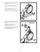
4. Using a plastic bag to keep your fingers clean, apply some of the included grease to the right Crank Arm (20). 4 Next, identify the Right Roller Arm (59), orient it as shown, and slide it onto the right Crank Arm (20). Attach the Right Roller Arm (59) with an M8 x 20mm Screw (95) and a Crank Cover (77). 45 20 Repeat this step for the Left Roller Arm (45). Grease 59 5. Tip: Avoid pinching the Main Wire (110). Have a second person hold the Upright (4) on the Frame (1).
6. Locate the wire tie (A) in the lower end of the Upright (4). Tie the wire tie to the Main Wire (110) as shown. Then, pull the upper end of the wire tie until the Main Wire is routed through the Upright. 6 A Tip: To prevent the Main Wire (110) from falling into the Upright (4), secure the Main Wire with the wire tie (A). 4 110 7. Apply grease to the axle on the right side of the Upright (4). A 7 Next, slide a Pivot Spacer (54) onto the right side of the Upright (4).
8. Orient the Right Pedal Arm (58) as shown, and then apply grease to the axle. 8 Insert the Right Pedal Arm (58) into the Right Upper Body Leg (60) and into the Right Roller Arm (59). Attach the Right Pedal Arm (58) to the Right Roller Arm (59) with an M8 x 20mm Flat Head Screw (120) and a Retainer (55); make sure that the flat side (B) of the Retainer is facing the Right Roller Arm. 44 60 120 Repeat this step for the Left Pedal Arm (44). 55 59 B Grease 9. Apply grease to a Pedal Arm Axle (64).
10. See step 5. Tighten the four M10 x 25mm Screws (92). 10 7 Next, untie and discard the wire tie on the Main Wire (110). While a second person holds the Console (7) near the Upright (4), connect the wires (C) on the Console to the Main Wire (110) and to the Pulse Wire (63) in the Upright. 63 110 4 101 C Insert the excess wire into the Upright (4) or into the Console (7). 92 Tip: Avoid pinching the wires.
12. Orient the Accessory Tray (37) as shown, and attach it to the Upright (4) with two M4 x 16mm Screws (101). 12 4 37 101 13. Orient a Lower Tray Cover (81) as shown, and attach it to the right side of the Accessory Tray (37) with two M4 x 16mm Screws (101). 13 Repeat this step on the other side of the elliptical. 37 81 101 14. Identify the Right Upper Body Arm (61), orient it as shown, and insert it into the Right Upper Body Leg (60).
. Orient the Front Shield Cover (117) and the Center Shield Cover (75) around the Upright (4). Then, attach them to each other with two M4 x 16mm Screws (101). 15 Avoid pinching the wires Tip: Avoid pinching the wires. Press the Front Shield Cover (117) and the Center Shield Cover (75) into the Left and Right Shields (73, 74). 4 73, 74 117 101 75 16. Identify the Right Leg Inner Cover (83), orient it as shown, and insert it through the Right Upper Body Leg (60).
17. Orient the Right Arm Front and Rear Covers (65, 66) around the Right Upper Body Leg (60) as shown, and then attach them with two M4 x 16mm Screws (101). 17 Repeat this step on the other side of the elliptical. 65 101 60 66 18. Make sure that all parts are properly tightened. Extra parts may be included. Place a mat beneath the elliptical to protect the floor.
HOW TO USE THE ELLIPTICAL HOW TO PLUG IN THE POWER CORD A temporary adapter (C) may be used to connect the power cord to a 2-pole receptacle (D) as shown at the right if a properly grounded outlet is not available. This product must be grounded. If it should malfunction or break down, grounding provides a path of least resistance for electric current to reduce the risk of electric shock. The power cord has a plug with a grounding pin.
HOW TO MOVE THE ELLIPTICAL HOW TO LEVEL THE ELLIPTICAL Due to the size and weight of the elliptical, moving it requires two persons. Stand in front of the elliptical, hold the upright (G), and place one foot against one of the wheels (H). Pull on the upright and have a second person lift the handle (I) until the elliptical will roll on the wheels. Carefully move the elliptical to the desired location, and then lower it to the floor.
HOW TO EXERCISE ON THE ELLIPTICAL THE OPTIONAL TABLET HOLDER To mount the elliptical, hold the handlebars (M) or the upper body arms (N) and step onto the pedal (O) that is in the lower position. Then, step onto the other pedal. Push the pedals until they begin to move with a continuous motion. Note: The pedals can turn in either direction. It is recommended that you turn the pedals in the direction shown by the arrow; however, for variety, you can turn the pedals in the opposite direction.
HOW TO USE THE CONSOLE CONSOLE DIAGRAM FEATURES OF THE CONSOLE When you use the manual mode of the console, you can change the resistance of the pedals and the incline of the ramp with the touch of a button. The advanced console offers an array of features designed to make your workouts more effective and enjoyable. While you exercise, the console will display continuous exercise feedback. You can even measure your heart rate using the handgrip heart rate monitor or a compatible heart rate monitor.
HOW TO TURN ON THE POWER HOW TO USE THE TOUCH SCREEN IMPORTANT: If the elliptical has been exposed to cold temperatures, allow it to warm to room temperature before you turn on the power. If you do not do this, you may damage the console or other electrical components. The console features a tablet with a full-color touch screen. The following information will help you use the touch screen: Plug in the power cord (see HOW TO PLUG IN THE POWER CORD on page 17).
HOW TO SET UP THE CONSOLE The console is now ready for you to begin working out. The following pages explain the workouts and other features that the console offers. Before you use the elliptical for the first time, set up the console. To use the manual mode, see this page. To use a featured workout or an onboard workout, see page 24. To create a draw-your-own-map workout, see page 26. To use an iFit workout, see page 27. 1. Connect to your wireless network.
If there are sheets of plastic on the metal contacts (B) on the handgrip heart rate monitor, remove the plastic. To meaB sure your heart rate, hold the handgrip heart rate monitor with your palms resting against the contacts. Avoid moving your hands or gripping the contacts tightly. To vary the motion of the pedals, you can change the incline of the ramp by pressing one of the numbered Ramp buttons or by pressing the Ramp increase and decrease buttons.
HOW TO USE A FEATURED WORKOUT OR AN ONBOARD WORKOUT To draw your own map for a workout, see HOW TO CREATE A DRAW-YOUR-OWN-MAP WORKOUT on page 26. 1. Touch the screen or press any button on the console to turn on the console. See HOW TO TURN ON THE POWER on page 21. Note: It may take a few moments for the console to be ready for use.
If the resistance level and/or incline level is too high or too low, you can manually override the setting by pressing the Resistance buttons or the Ramp buttons. If you press a Resistance button, you can then manually control the resistance level (see step 3 on page 22). If you press a Ramp button, you can then manually control the incline level (see step 3 on page 22). To return to the programmed resistance and/or incline settings of the workout, touch Follow Workout.
HOW TO CREATE A DRAW-YOUR-OWN-MAP WORKOUT If you make a mistake, touch Undo in the map options. 1. Touch the screen or press any button on the console to turn on the console. The screen will display the elevation and distance statistics for your workout. See HOW TO TURN ON THE POWER on page 21. Note: It may take a few moments for the console to be ready for use. 4. Save your workout. Touch Save New Workout to save your workout. If desired, enter a title and description for your workout.
HOW TO USE AN IFIT WORKOUT 4. Select an iFit workout that you have previously added to your schedule on iFit.com. To use an iFit workout, the console must be connected to a wireless network (see HOW TO CONNECT TO A WIRELESS NETWORK on page 29). An iFit account is also required. IMPORTANT: Before iFit workouts will load, you must add them to your schedule on iFit.com (see step 1). 1. Add workouts to your schedule on iFit.com. To load an iFit workout from iFit.
HOW TO CHANGE CONSOLE SETTINGS The console can display speed and distance in either standard or metric units of measurement. IMPORTANT: Some of the settings and features described may not be enabled. Occasionally, a firmware update may cause your console to function slightly differently. 4. View machine information or console app information. Touch Equipment Info, and then touch Machine Info or App Info to view information about your elliptical or about the console app. 1.
HOW TO CONNECT TO A WIRELESS NETWORK Note: You must have your own wireless network and an 802.11b/g/n router with SSID broadcast enabled (hidden networks are not supported). To use iFit workouts and to use several other features of the console, the console must be connected to a wireless network. When a list of networks appears, touch the desired network. Note: You will need to know your network name (SSID). If your network has a password, you will also need to know the password. 1.
HOW TO USE THE SOUND SYSTEM THE OPTIONAL CHEST HEART RATE MONITOR To play music or audio books through the console sound system while you exercise, plug a 3.5 mm male to 3.5 mm male audio cable (not included) into the jack on the console and into a jack on your personal audio player; make sure that the audio cable is fully plugged in. Note: To purchase an audio cable, see your local electronics store.
FCC INFORMATION This equipment has been tested and found to comply with the limits for a Class B digital device, pursuant to Part 15 of the FCC Rules. These limits are designed to provide reasonable protection against harmful interference in a residential installation. This equipment generates, uses, and can radiate radio frequency energy and, if not installed and used in accordance with the instructions, may cause harmful interference to radio communications.
MAINTENANCE AND TROUBLESHOOTING MAINTENANCE to the factory default settings. IMPORTANT: Doing this will erase all custom settings you have made A to the console. Resetting the console requires two people. First, press the power switch into the off position. Next, locate the small reset opening (A) on the back or the side of the console. Using a bent paper clip, press and hold the reset button inside the opening, and have a second person press the power switch into the on position.
HOW TO ADJUST THE REED SWITCH HOW TO ADJUST THE DRIVE BELT If the console does not display correct feedback, the reed switch should be adjusted. To adjust the reed switch, first press the power switch and unplug the power cord. If the pedals slip while you are pedaling, even while the resistance is adjusted to the highest level, the drive belt may need to be adjusted. To adjust the drive belt, first press the power switch and unplug the power cord.
EXERCISE GUIDELINES Burning Fat—To burn fat effectively, you must exercise at a low intensity level for a sustained period of time. During the first few minutes of exercise, your body uses carbohydrate calories for energy. Only after the first few minutes of exercise does your body begin to use stored fat calories for energy. If your goal is to burn fat, adjust the intensity of your exercise until your heart rate is near the lowest number in your training zone.
PART LIST Key No. Qty. 1 2 3 4 5 6 7 8 9 10 11 12 13 14 15 16 17 18 19 20 21 22 23 24 25 26 27 28 29 30 31 32 33 34 35 36 37 38 39 40 41 42 43 44 45 46 47 48 49 50 1 1 1 1 6 1 1 2 1 1 1 1 1 2 1 2 1 1 1 2 1 1 2 1 1 7 2 1 1 4 3 2 2 2 2 1 1 1 1 2 1 1 2 1 1 1 1 1 1 6 Model No. PFEL59920.0 R0919A Description Key No. Qty.
Key No. Qty. 101 102 103 104 105 106 107 108 109 110 111 112 113 114 115 116 117 118 119 120 121 122 43 6 11 4 1 1 1 2 2 1 2 2 1 1 4 2 1 1 1 2 8 1 Description Key No. Qty.
52 49 76 140 95 47 21 44 45 46 68 67 70 72 127 101 54 118 71 101 50 75 5 116 124 101 50 101 5 101 7 117 101 73 80 63 37 35 4 85 35 101 81 101 101 101 92 101 79 EXPLODED DRAWING A Model No. PFEL59920.
104 101 2 15 33 16 131 10 130 26 135 16 131 108 27 30 31 42 20 50 31 9 119 1 41 38 40 78 86 136 121 101 130 39 102 106 24 128 105 22 110 103 91 121 122 90 92 94 36 26 88 89 101 102 28 13 82 84 40 93 114 14 6 103 103 19 82 43 48 90 90 14 12 11 43 99 25 17 115 115 113 86 18 23 78 20 107 112 26 104 135 108 26 30 109 34 EXPLODED DRAWING B Model No. PFEL59920.
5 95 74 98 8 126 5 51 101 101 120 39 56 101 3 137 132 139 29 138 127 50 59 138 56 124 116 53 95 55 5 50 126 103 101 71 111 57 123 103 134 133 32 61 95 125 77 62 26 58 87 66 95 54 101 82 102 57 83 100 129 96 57 64 82 65 60 100 97 101 101 69 EXPLODED DRAWING C Model No. PFEL59920.
ORDERING REPLACEMENT PARTS To order replacement parts, please see the front cover of this manual.