Model No. PFEL69720-INT.2 Serial No. Write the serial number in the space above for reference. USER’S MANUAL Serial Number Decal CUSTOMER SERVICE UNITED KINGDOM Call: 0330 123 1045 From Ireland: 053 92 36102 Website: iconsupport.eu E-mail: csuk@iconeurope.com Write: ICON Health & Fitness, Ltd. Unit 4, Westgate Court Silkwood Park OSSETT WF5 9TT UNITED KINGDOM AUSTRALIA Call: 1800 993 770 E-mail: australiacc@iconfitness.
TABLE OF CONTENTS WARNING DECAL PLACEMENT . . . . . . . . . . . . . . . . . . . . . . . . . . . . . . . . . . . . . . . . . . . . . . . . . . . . . . . . . . . . . . .2 IMPORTANT PRECAUTIONS . . . . . . . . . . . . . . . . . . . . . . . . . . . . . . . . . . . . . . . . . . . . . . . . . . . . . . . . . . . . . . . . . . 3 BEFORE YOU BEGIN. . . . . . . . . . . . . . . . . . . . . . . . . . . . . . . . . . . . . . . . . . . . . . . . . . . . . . . . . . . . . . . . . . . . . . . .
IMPORTANT PRECAUTIONS WARNING: To reduce the risk of serious injury, read all important precautions and instructions in this manual and all warnings on your elliptical before using your elliptical. ICON assumes no responsibility for personal injury or property damage sustained by or through the use of this product. 1. It is the responsibility of the owner to ensure that all users of the elliptical are adequately informed of all precautions. parts immediately. Use only manufacturersupplied parts. 9.
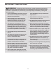
BEFORE YOU BEGIN Thank you for selecting the revolutionary NORDICTRACK® ENDURANCE 520 E elliptical. The ENDURANCE 520 E elliptical provides an impressive selection of features designed to make your workouts at home more effective and enjoyable. reading this manual, please see the front cover of this manual. To help us assist you, note the product model number and serial number before contacting us. The model number and the location of the serial number decal are shown on the front cover of this manual.
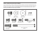
PART IDENTIFICATION CHART Use the drawings below to identify the small parts needed for assembly. The number in parentheses below each drawing is the key number of the part, from the PART LIST near the end of this manual. The number following the key number is the quantity needed for assembly. Note: If a part is not in the hardware kit, check to see if it has been preassembled. Extra parts may be included.
ASSEMBLY • Assembly requires two persons. • In addition to the included tool(s), assembly requires the following tools: • Place all parts in a cleared area and remove the packing materials. Do not dispose of the packing materials until you finish all assembly steps. one Phillips screwdriver two adjustable wrenches • Left parts are marked “L” or “Left” and right parts are marked “R” or “Right.” one rubber mallet Assembly may be easier if you have a set of wrenches.
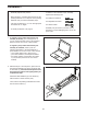
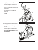
3. With the help of a second person, place some of the packing materials (not shown) under the front of the Frame (1). Have the second person hold the Frame to prevent it from tipping while you complete this step. 3 6 104 Attach the Front Stabilizer (6) to the Frame (1) with two M10 x 115mm Screws (104). Then, remove the packing materials from under the front of the Frame (1). 1 4. Identify the Right Roller Arm (59), orient it as shown, and slide it onto the right Crank Arm (20).
5. Tip: Avoid pinching the Main Wire (110). Have a second person hold the Upright (4) on the Frame (1). 5 Avoid pinching the Main Wire (110) Tip: Two M10 x 25mm Screws (92) are preattached to the Frame (1). 92 Attach the Upright (4) to the Frame (1) with two additional M10 x 25mm Screws (92); start both Screws, and then tighten all four Screws. 4 110 92 1 6. Locate the wire tie (A) in the lower end of the Upright (4). Tie the wire tie to the Main Wire (110) as shown.
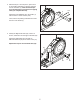
7. Apply grease to the axle on the right side of the Upright (4). 7 Next, slide a Pivot Spacer (54) onto the right side of the Upright (4). Then, identify the Right Upper Body Leg (60), orient it as shown, and slide it onto the right side of the Upright (4). 4 46 Attach the Right Upper Body Leg (60) with an M8 x 13mm Screw (82) and an M8 x 28mm Washer (97). Grease 54 60 97 82 Repeat this step for the Left Upper Body Leg (46). 8.
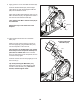
9. Apply grease to one of the Pedal Arm Axles (64). 9 Insert the Pedal Arm Axle (64) into the Right Upper Body Leg (60) and the Right Pedal Arm (58) from the direction shown. Next, slide an M8 x 22mm Washer (129) onto an M8 x 13mm Screw (82), and tighten the Screw a few turns into the Pedal Arm Axle (64). Then, tighten both M8 x 13mm Screws (82) at the same time. 82 60 129 64 Repeat this step on the other side of the elliptical. 58 10. Untie and discard the wire tie on the Main Wire (110).
. Orient the Accessory Tray (37) as shown, and attach it to the Upright (4) with two M4 x 16mm Screws (101). 11 4 37 101 12. Orient a Lower Tray Cover (81) as shown, and attach it to the right side of the Accessory Tray (37) with two M4 x 16mm Screws (101). 12 Repeat this step on the other side of the elliptical.
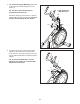
13. Identify the Right Upper Body Arm (61), orient it as shown, and slide it onto the Right Upper Body Leg (60). 13 Attach the Right Upper Body Arm (61) with two M8 x 45mm Bolts (96) and two M8 Locknuts (102); make sure that the Locknuts are in the hexagonal holes (C). 96 Repeat this step for the Left Upper Body Arm (47). 47 60 61 102 14. Orient the Front Shield Cover (117) and the Center Shield Cover (75) around the Upright (4) as shown.
15. Identify the Right Leg Inner Cover (83), orient it as shown, and insert it through the Right Upper Body Leg (60). 15 Next, identify the Right Leg Outer Cover (69), orient it as shown, and press it onto the Right Leg Inner Cover (83). Attach the Right Leg Outer and Inner Covers (69, 83) to each other with an M4 x 16mm Screw (101). Repeat this step on the other side of the elliptical. 60 83 69 101 16.
17. Plug the Power Adapter (119) into the receptacle on the frame of the elliptical. 17 Note: To plug the Power Adapter (119) into an outlet, see HOW TO PLUG IN THE POWER ADAPTER on page 15. 119 18. Make sure that all parts are properly tightened before you use the elliptical. Place a mat beneath the elliptical to protect the floor. Note: Extra parts may be included.
HOW TO USE THE ELLIPTICAL HOW TO PLUG IN THE POWER ADAPTER HOW TO MOVE THE ELLIPTICAL IMPORTANT: If the elliptical has been exposed to cold temperatures, allow it to warm to room temperature before you plug in the power adapter (A). If you do not do this, you may damage the console displays or other electronic components. Due to the size and weight of the elliptical, moving it requires two persons. Stand in front of the elliptical, hold the upright (D), and place one foot against one of the wheels (E).
HOW TO CHANGE THE INCLINE OF THE RAMP HOW TO EXERCISE ON THE ELLIPTICAL To vary the motion of the pedals, you can change the incline of the ramp. To raise the ramp, press the latch button (G), and then pull the ramp handle (H) upward to the desired incline level. To mount the elliptical, hold the handlebars (I) or the upper body arms (J) and step onto the pedal (K) that is in the lower position. Then, step onto the other pedal. Push the pedals until they begin to move with a continuous motion.
HOW TO USE THE CONSOLE CONSOLE DIAGRAM FEATURES OF THE CONSOLE Each iFit workout automatically changes the resistance of the pedals as an iFit coach guides you through an immersive and effective video workout. The advanced console offers an array of features designed to make your workouts more effective and enjoyable. To use the manual mode, see page 18. To use the sound system, see page 20.
HOW TO USE THE MANUAL MODE Pulse (BPM and heart symbol)—Your heart rate when you use a compatible heart rate monitor (see step 5). 1. Begin pedaling or press any button on the console to turn on the console. Resistance (RESIST)—The resistance level of the pedals. When you turn on the console, the display will turn on. The console will then be ready for use. RPM—Your pedaling speed in revolutions per minute (RPM). 2. Select the manual mode.
To customize the scan mode, first press the Display button repeatedly until the workout information that you want to add to or remove from the scan cycle appears in the display. A compatible heart rate monitor is included with some models. If a heart rate monitor is included, see THE HEART RATE MONITOR in this manual to learn how to use it. Next, press the Add/Remove button (C) to add or remove that workout information from the scan cycle.
HOW TO USE THE SOUND SYSTEM 3. Connect your smart device to the console. To play music or audio books through the console sound system while you exercise, plug a 3.5 mm male to 3.5 mm male audio cable (not included) into the jack on the console and into a jack on your personal audio player; make sure that the audio cable is fully plugged in. Note: To purchase an audio cable, see your local electronics store. Press the iFit Sync button on the console; the console pairing number will appear in the display.
Note: The calorie goal shown in the workout description is an estimate of the number of calories that you will burn during the workout. The actual number of calories that you burn will depend on various factors, such as your weight. In addition, if you manually change the resistance level during the workout, the number of calories you burn will be affected. HOW TO CONNECT YOUR HEART RATE MONITOR TO THE CONSOLE The console is compatible with all Bluetooth Smart heart rate monitors.
HOW TO CHANGE CONSOLE SETTINGS Total Distance—The letters MI or KM will appear in the display. The display will show the total distance (in miles or kilometers) that the elliptical has been pedaled. 1. Select the settings mode. To select the settings mode, press the Settings button. The first settings screen will appear in the display. Note: If you are using the manual mode or an iFit workout, end your workout before you press the Settings button.
MAINTENANCE AND TROUBLESHOOTING MAINTENANCE Next, locate the Reed Switch (38). Turn the Pulley (19) until a Magnet (43) is aligned with the Reed Switch. Regular maintenance is important for optimal performance and to reduce wear. Inspect and properly tighten all parts each time the elliptical is used. Replace any worn parts immediately. Use only manufacturer-supplied parts. To clean the elliptical, use a damp cloth and a small amount of mild soap.
HOW TO ADJUST THE DRIVE BELT Next, locate and loosen the Idler Screw (89). Tighten the Drive Belt Adjustment Screw (91) until the Drive Belt (113) is tight. Then, retighten the Idler Screw. If the pedals slip while you are pedaling, even while the resistance is adjusted to the highest level, the drive belt may need to be adjusted. To adjust the drive belt, first unplug the power adapter. Next, locate the Access Cover (3) on the Right Shield (74).
EXERCISE GUIDELINES Aerobic Exercise—If your goal is to strengthen your cardiovascular system, you must perform aerobic exercise, which is activity that requires large amounts of oxygen for prolonged periods of time. For aerobic exercise, adjust the intensity of your exercise until your heart rate is near the highest number in your training zone. WARNING: Before beginning this or any exercise program, consult your physician.
SUGGESTED STRETCHES The correct form for several basic stretches is shown at the right. Move slowly as you stretch; never bounce. 1. Toe Touch Stretch Stand with your knees bent slightly and slowly bend forward from your hips. Allow your back and shoulders to relax as you reach down toward your toes as far as possible. Hold for 15 counts, then relax. Repeat 3 times. Stretches: Hamstrings, back of knees and back. 1 2. Hamstring Stretch Sit with one leg extended.
PART LIST Key No. Qty. 1 2 3 4 5 6 7 8 9 10 11 12 13 14 15 16 17 18 19 20 21 22 23 24 25 26 27 28 29 30 31 32 33 34 35 36 37 38 39 40 41 42 43 44 45 46 47 48 49 50 1 1 1 1 6 1 1 2 2 1 1 1 1 1 1 2 1 1 1 2 – 1 2 1 1 4 2 1 1 4 2 4 2 2 6 1 1 1 1 2 1 1 2 1 1 1 1 1 1 6 Model No. PFEL69720-INT.2 R0521A Description Key No. Qty.
Key No. Qty. 101 102 103 104 105 106 107 108 109 110 111 112 113 114 115 116 46 6 8 4 1 1 1 2 2 1 1 2 1 5 2 2 Description Key No. Qty.
52 95 76 49 51 70 32 82 44 77 101 80 47 62 29 8 56 64 102 95 120 98 55 45 68 96 100 123 97 99 82 71 72 50 127 118 54 101 129 46 100 67 101 35 101 5 116 35 101 124 75 50 35 5 101 101 7 73 101 117 63 4 37 85 101 81 101 101 92 EXPLODED DRAWING A Model No. PFEL69720-INT.
31 30 104 27 10 101 15 101 27 125 114 14 31 115 11 48 2 101 114 16 94 101 33 79 13 122 30 121 106 105 42 20 24 128 26 90 125 16 1 17 108 101 114 12 41 9 40 78 111 110 1 38 50 86 101 91 88 22 39 119 28 102 36 92 89 82 84 40 93 82 43 102 43 9 25 113 19 6 86 78 23 20 112 18 26 104 107 108 90 26 109 30 34 EXPLODED DRAWING B Model No. PFEL69720-INT.
95 5 98 74 8 126 5 51 101 101 120 5 35 31 3 56 35 116 53 95 55 56 101 50 126 103 52 50 127 59 124 35 103 101 32 101 71 99 32 29 123 58 77 87 80 95 61 57 66 83 54 62 57 97 129 100 96 60 82 102 100 101 65 101 82 64 101 69 EXPLODED DRAWING C Model No. PFEL69720-INT.
ORDERING REPLACEMENT PARTS To order replacement parts, please see the front cover of this manual.