
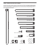
User's Manual

8
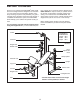
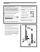
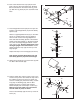
6. Lubricate an M10 x 180mm Bolt (55) with grease.
Attach the Backrest (12) to the Bench Frame (5)
with the Bolt, two M10 W
ashers (6), and an M10
Nylon Locknut (11).
Do not overtighten the Nylon
Locknut; the Backrest must be able to pivot
easily.
Secure the Backrest (12) to the Bench Frame (5)
by inserting the Locking Pin (27) through one of the
three sets of holes in the adjustment tubes and
through the tube inside the Bench Frame. Make
sure that the Locking Pin is completely inserted
through both adjustment tubes.
Tighten the four M6 x 38mm Screws (39) used
in step 5.
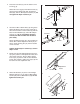
7. Attach the Seat (17) to the Bench Frame (5) with
four M6 x 16mm Screws (26).
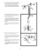
8. Tap two 50mm Round Inner Caps (25) into the
ends of the Leg Lever (7). Insert a 25mm Round
Inner Cap (36) into the end of the weight tube on
the Leg Lever. Press the 25mm Angle Cap (35)
onto the other end of the weight tube.
Lubricate an M10 x 95mm Bolt (56) with grease.
Attach the Leg Lever (7) to the Front Leg (3) with
the Bolt and an M10 Nylon Locknut (11). Do not
overtighten the Nylon Locknut; the Leg Lever
must be able to pivot easily
.
11
6
5
Adjustment
Tubes
12
27
6
5
17
26
26
56
25
Weight Tube
Lubricate
7
36
25
35
3
11
7
8
55
6
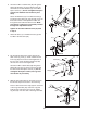
9.
Slide the Oval Insert (52) into the Front Leg (3) so
that the tab snaps into the slot in the Front Leg.
Press a 19mm Round Inner Cap (32) into each end
of the Long Pad Tube (30). Insert the Long Pad
Tube into the holes in the Front Leg (3). Slide a
Leg Pad (22) onto each side of the Long Pad Tube.
22
32
22
3
52
T
ab
30
9