
User's Manual

10
11
12
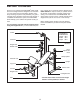
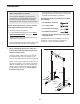
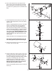
10. Insert 19mm Round Inner Caps (32) into both
ends of the two Short Pad Tubes (33). Slide the
Short Pad
Tubes into the holes in the Leg Lever
(7). Slide two Leg Pads (22) onto each Short Pad
T
ube.
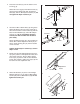
11. Press Weight Rest Inserts (20) into the tops and
bottoms of the Weight Rests (19) and the Safety
Spotters (40).
Attach a Large Adjustment Knob (21) to the weld-
ed nut on a Safety Spotter (40), and tighten it
with a wrench. Pull out the Large Adjustment
Knob and slide the Safety Spotter to the desired
height on the Right Upright (1). Engage the Knob
into a hole in the Right Upright and turn it clock-
wise until it is tight.
Attach a Weight Rest (19) to
the Right Upright in the same manner. Insert a
76mm Round Inner Cap (18) into the top of the
Right Upright.
Repeat this step for the Left Upright (not shown).
Note: Always set both Weight Rests (19) and
both Safety Spotters (40) at the same height.
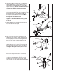
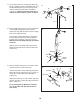
12. Attach the Curl Pad (9) to the Curl Frame (8) with
two M6 x 16mm Screws (26).
13. Find the Cable (49); note that it has a ball on one
end and a loop on the other
. Slide the loop end of
the Cable through the slot in the Lat
T
ower (41)
and over a Pulley (45). Attach the Pulley, a Cable
Trap (53), two Bushings (46), and two M10
W
ashers (6) to the Lat Tower with an M10 x
85mm Bolt (58) and an M10 Nylon Locknut (1
1).
Make sure that the Cable Trap is oriented to
hold the Cable in place, as shown.
Press an Oval Endcap (43) into the top of the Lat
Tower (41).
22
32
33
32
32
22
22
18
20
20
21
21
19
40
20
1
9
26
8
33
7
9
46
46
11
58
49
41
45
6
6
43
53
13