Model No. PFEVEL72912.0 Serial No. Write the serial number in the space above for reference. USER’S MANUAL Serial Number Decal (under frame) QUESTIONS? If you have questions, or if there are missing parts, please contact us: UNITED KINGDOM Call: 08457 089 009 From Ireland: 053 92 36102 Website: www.iconsupport.eu E-mail: csuk@iconeurope.com Write: ICON Health & Fitness, Ltd. c/o HI Group PLC Express Way CASTLEFORD WF10 5QJ UNITED KINGDOM AUSTRALIA Call: 1800 993 770 E-mail: australiacc@iconfitness.
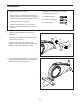
TABLE OF CONTENTS WARNING DECAL PLACEMENT . . . . . . . . . . . . . . . . . . . . . . . . . . . . . . . . . . . . . . . . . . . . . . . . . . . . . . . . . . . . . . .2 IMPORTANT PRECAUTIONS. . . . . . . . . . . . . . . . . . . . . . . . . . . . . . . . . . . . . . . . . . . . . . . . . . . . . . . . . . . . . . . . . . 3 BEFORE YOU BEGIN. . . . . . . . . . . . . . . . . . . . . . . . . . . . . . . . . . . . . . . . . . . . . . . . . . . . . . . . . . . . . . . . . . . . . . . .4 PART IDENTIFICATION CHART.
IMPORTANT PRECAUTIONS WARNING: To reduce the risk of serious injury, read all important precautions and instructions in this manual and all warnings on your elliptical before using your elliptical. ICON assumes no responsibility for personal injury or property damage sustained by or through the use of this product. 1. Before beginning any exercise program, consult your physician. This is especially important for persons over age 35 or persons with pre-existing health problems. 9.
BEFORE YOU BEGIN Thank you for selecting the new PROFORM® 220 ZLE elliptical. The 220 ZLE provides a selection of features designed to make your workouts at home more effective and enjoyable. manual. To help us assist you, note the product model number and serial number before contacting us. The model number and the location of the serial number decal are shown on the front cover of this manual. For your benefit, read this manual carefully before you use the elliptical.
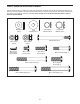
PART IDENTIFICATION CHART Use the drawings below to identify the small parts needed for assembly. The number in parentheses below each drawing is the key number of the part, from the PART LIST near the end of this manual. The number following the key number is the quantity needed for assembly. Note: If a part is not in the hardware kit, check to see if it has been preassembled.
ASSEMBLY • Assembly requires two persons. In addition to the included tool(s), assembly requires the following tools: • Place all parts in a cleared area and remove the packing materials. Do not dispose of the packing materials until you complete all assembly steps. one adjustable wrench one Phillips screwdriver • To identify small parts, see page 5. one rubber mallet Assembly may be easier if you have a set of wrenches. To avoid damaging parts, do not use power tools. 1.
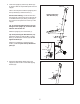
3. Orient the Upright (2) and the Top Shield (41) as shown. Slide the Top Shield upward onto the Upright. 3 Wire Tie Have a second person hold the Upright (2) and the Top Shield (41) near the Frame (1). Avoid pinching the Wire Harness (73) See the inset drawing. Locate the wire tie in the Upright (2). Tie the lower end of the wire tie to the Wire Harness (73). Next, pull the upper end of the wire tie upward out of the top of the Upright.
5. Identify the Left and Right Handlebars (85, 86), which are marked with “Left” and “Right” stickers. 5 While a second person holds the Left and Right Handlebars (85, 86) near the Upright (2), insert the Sensor Wires (84) into the holes in the Upright and pull them upward out of the Upright. 84 85 84 38 Tip: Avoid pinching the wires. Attach the Left and Right Handlebars (85, 86) to the Upright (2) with an M8 x 77mm Bolt (79) and an M8 Locknut (38). Do not tighten the Bolt yet.
8. Insert the excess wire into the Console (23) or the Upright (2). 8 23 Avoid pinching the wires Press the Rear Upright Cover (75) into the Upright (2). Have a second person hold the Rear Upright Cover in place. 2 Tip: Avoid pinching the wires. Attach the Console (23) to the Upright (2) with four M4 x 16mm Self-tapping Screws (52). 75 52 9. Finish attaching the Left and Right Handlebars (85, 86) to the Upright (2) with an M8 x 77mm Bolt (79) and an M8 Locknut (38).
. Attach the Front Upright Cover (81) to the Upright (2) and the Rear Upright Cover (75) with two M4 x 16mm Self-tapping Screws (52). 10 81 52 75 2 11. Identify the Right Upper Body Arm (8), which is marked with an “R” sticker. 11 Slide an Upper Body Arm Cover (28) upward onto the Right Upper Body Arm (8). 6 Slide the Right Upper Body Arm (8) onto an Upper Body Leg (5).
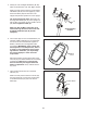
12. Insert the Pivot Axle (26) into the Upright (2), and center the Pivot Axle. 12 Using a small plastic bag to keep your fingers clean, apply a generous amount of the included grease to both ends of the Pivot Axle (26). Orient an Upper Body Arm Spacer (47) so that the arrow points toward the floor. Slide the Upper Body Arm Spacer onto the right side of the Pivot Axle (26). Repeat this action on the other side of the elliptical.
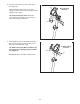
14. Apply a small amount of grease to the axle on the Right Crank Arm (16) and to a Large Wave Washer (76). 14 Grease Slide the Large Wave Washer (76) and the Right Pedal Arm (12) onto the axle on the Right Crank Arm (16). 76 Slide an M10 Washer (35) onto an M10 x 25mm Screw (40), and tighten the Screw into the axle. 16 Then, press a Pedal Arm Cap (74) into the Right Pedal Arm (12). 35 Repeat this step on the other side of the elliptical. 15. Apply a small amount of grease to an M6 Bolt Set (25).
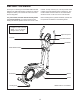
HOW TO USE THE ELLIPTICAL HOW TO MOVE THE ELLIPTICAL HOW TO EXERCISE ON THE ELLIPTICAL Due to the size and weight of the elliptical, moving it requires two persons. Stand in front of the elliptical, hold the upright, and place one foot against one of the wheels. Pull on the upright and have a second person lift the rear stabilizer until the elliptical will roll on the wheels. Carefully move the elliptical to the desired location, and then lower it to the floor.
CONSOLE DIAGRAM HOW TO USE THE MANUAL MODE 1. Turn on the console. To turn on the console, press the On/Reset button or begin pedaling. The entire display will turn on for a moment; the console will then be ready for use. 2. Select the manual mode. When you turn on the console, the manual mode will be selected. If you have selected a workout, reselect the manual mode by pressing any of the Quick Onboard Workouts buttons repeatedly until zeros appear in the display. 3.
Pulse—This display shows your heart rate when you use the handgrip heart rate monitor. To reset the display, press the On/Reset button. To pause the console, stop pedaling. When the console is paused, the time will flash in the display. To continue your workout, simply resume pedaling. Scan—When you select this display option, the upper section of the display will show both time and distance information, and the lower left section of the display will show calories information.
HOW TO USE A QUICK ONBOARD WORKOUT 2. Select a quick onboard workout. The target speed settings for the workout will be shown by the target meter in the display. The RPM meter will show your actual pedaling speed. To select a quick onboard workout, press the desired Quick Onboard Workouts button. The name of the workout will appear in the display. As the target meter changes in height during the workout, adjust your pedaling speed so that the same number of bars appears in both meters.
MAINTENANCE AND TROUBLESHOOTING Inspect and tighten all parts of the elliptical regularly. Replace any worn parts immediately. Note: For clarity, the right pedal disc is shown removed in the drawing below. To clean the elliptical, use a damp cloth and a small amount of mild dish soap. IMPORTANT: Keep liquids away from the console and keep the console out of direct sunlight. During storage, remove the batteries from the console. Locate the Reed Switch (53).
HOW TO ADJUST THE DRIVE BELT Loosen the M8 x 22mm Flat Head Screw (65) and turn the M10 x 60mm Bolt (62) until the Drive Belt (19) is tight. If you can feel the pedals slip while you are pedaling, even when the resistance is adjusted to the highest level, the drive belt may need to be adjusted. To adjust the drive belt, you must remove the left pedal arm, the left pedal disc, and the left shield. First, see steps 14 and 15 on page 12 and remove the Left Pedal Arm (11).
EXERCISE GUIDELINES Burning Fat—To burn fat effectively, you must exercise at a low intensity level for a sustained period of time. During the first few minutes of exercise, your body uses carbohydrate calories for energy. Only after the first few minutes of exercise does your body begin to use stored fat calories for energy. If your goal is to burn fat, adjust the intensity of your exercise until your heart rate is near the lowest number in your training zone.
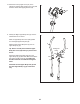
SUGGESTED STRETCHES The correct form for several basic stretches is shown at the right. Move slowly as you stretch—never bounce. 1. Toe Touch Stretch Stand with your knees bent slightly and slowly bend forward from your hips. Allow your back and shoulders to relax as you reach down toward your toes as far as possible. Hold for 15 counts, then relax. Repeat 3 times. Stretches: Hamstrings, back of knees and back. 1 2. Hamstring Stretch Sit with one leg extended.
PART LIST Key No. Qty. 1 2 3 4 5 6 7 8 9 10 11 12 13 14 15 16 17 18 19 20 21 22 23 24 25 26 27 28 29 30 31 32 33 34 35 36 37 38 39 40 41 42 43 44 45 46 1 1 1 1 2 1 2 1 1 1 1 1 1 1 2 1 1 1 1 2 2 1 1 2 2 1 6 2 1 2 2 1 2 4 7 2 2 9 2 2 1 2 2 2 1 2 Model No. PFEVEL72912.0 R0312A Description Key No. Qty.
EXPLODED DRAWING A Model No. PFEVEL72912.
EXPLODED DRAWING B Model No. PFEVEL72912.
ORDERING REPLACEMENT PARTS To order replacement parts, please see the front cover of this manual.