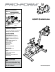
Model No. PFEVEX79911.1 Serial No. Write the serial number in the space above for reference. USER’S MANUAL Serial Number Decal QUESTIONS? If you have questions, or if there are missing parts, please contact us: UNITED KINGDOM Call: 08457 089 009 From Ireland: 053 92 36102 Website: www.iconsupport.eu E-mail: csuk@iconeurope.com Write: ICON Health & Fitness, Ltd. c/o HI Group PLC Express Way CASTLEFORD WF10 5QJ UNITED KINGDOM AUSTRALIA Call: 1800 993 770 E-mail: australiacc@iconfitness.
TABLE OF CONTENTS WARNING DECAL PLACEMENT . . . . . . . . . . . . . . . . . . . . . . . . . . . . . . . . . . . . . . . . . . . . . . . . . . . . . . . . . . . . . . .2 IMPORTANT PRECAUTIONS. . . . . . . . . . . . . . . . . . . . . . . . . . . . . . . . . . . . . . . . . . . . . . . . . . . . . . . . . . . . . . . . . . 3 BEFORE YOU BEGIN. . . . . . . . . . . . . . . . . . . . . . . . . . . . . . . . . . . . . . . . . . . . . . . . . . . . . . . . . . . . . . . . . . . . . . . .4 PART IDENTIFICATION CHART.
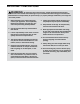
IMPORTANT PRECAUTIONS WARNING: To reduce the risk of serious injury, read all important precautions and instructions in this manual and all warnings on your exercise bike before using your exercise bike. ICON assumes no responsibility for personal injury or property damage sustained by or through the use of this product. 7. Inspect and properly tighten all parts regularly. Replace any worn parts immediately. 1. Before beginning any exercise program, consult your physician.
BEFORE YOU BEGIN Congratulations for selecting the revolutionary PROFORM® LE TOUR DE FRANCE® exercise bike. The LE TOUR DE FRANCE exercise bike is unlike any other exercise bike. With an incline system that automatically simulates actual road terrain, intelligent wind resistance, and an array of other features, the LE TOUR DE FRANCE exercise bike is designed to let you enjoy the outdoor cycling experience indoors. reading this manual, please see the front cover of this manual.
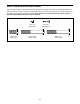
PART IDENTIFICATION CHART Use the drawings below to identify the small parts needed for assembly. The number in parentheses below each drawing is the key number of the part, from the PART LIST near the end of this manual. The number following the key number is the quantity needed for assembly. Note: If a part is not in the hardware kit, check to see if it has been preassembled. Extra parts may be included.
ASSEMBLY • Assembly requires two persons. • In addition to the included tool(s), assembly requires the following tools: • Place all parts in a cleared area and remove the packing materials. Do not dispose of the packing materials until you complete all assembly steps. one Phillips screwdriver one adjustable wrench • To identify small parts, see page 5. Assembly may be easier if you have a set of wrenches. To avoid damaging parts, do not use power tools. 1.
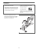
2. While a second person lifts the rear of the Base (1), attach the Rear Stabilizer (23) to the Base with two 3/8" x 2 1/4" Screws (74). 2 74 1 23 3. Orient the Seat Post (3) as shown. 3 Loosen the indicated Post Knob (47) and pull it outward. Then, insert the Seat Post (3) into the Frame (2). 3 Move the Seat Post (3) upward or downward to the desired position, release the Post Knob (47) into an adjustment hole in the Seat Post, and then tighten the Post Knob.
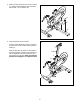
4. Orient the Seat Carriage (4) as shown. 4 Loosen the Seat Knob (29) and pull it downward. Then, slide the Seat Carriage (4) into the Seat Post (3). 3 92 4 Slide the Seat Carriage (4) to the desired position, release the Seat Knob (29) into one of the adjustment holes in the Seat Carriage, and then tighten the Seat Knob. Make sure that the Seat Knob is firmly engaged in an adjustment hole. 29 Holes Then, tighten a #8 x 1/4" Screw (92) into the underside of the Seat Carriage (4). 5.
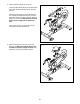
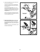
6. Orient the Handlebar Post (6) as shown. 6 Have a second person hold the Handlebar Post (6) near the Frame (2). Locate the wire tie in the Handlebar Post, and tie the lower end of the wire tie to the Lower Wire (69). Then, pull the upper end of the wire tie until the Lower Wire is routed through the Handlebar Post. Avoid pinching the Lower Wire (69) Holes 47 Tip: Avoid pinching the Lower Wire (69). Loosen the indicated Post Knob (47) and pull it outward.
8. Orient the Handlebar Cover (67) as shown and hold it near the Handlebar (7). Connect the receiver wire (B) to the Extension Wire (102). Carefully insert the excess wire into the Handlebar (7). 67 B 102 7 Tip: Avoid pinching the wires. Insert a #8 x 5/8" Screw (94) upward into the front hole in the Handlebar (7). Set the Handlebar Cover (67) on the Handlebar, and tighten the Screw into the Handlebar Cover.
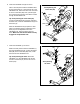
10. Plug the Left and Right Shifter Wires (70, 81) in the Handlebar (7) into the receptacles marked “R” and “L” on the back of the Console (9). 10 9 Next, plug the Extension Wire (102) into the receptacle marked “Pulse.” 81 Plug the Upper Wire (68) into the remaining receptacle. 7 11. Attach the back of the Console (9) to the Console with the two screws (C) that you removed earlier. 102 11 Next, attach the Tray (8) to the back of the Console (9) with four #8 x 5/8" Screws (94).
. Identify the Left Pedal (61), which is marked with an “L.” Using an adjustable wrench, firmly tighten the Left Pedal (61) counterclockwise into the Left Crank Arm (63). Tighten the Right Pedal (not shown) clockwise into the Right Crank Arm (not shown). 12 63 61 13. Make sure that all parts are properly tightened before you use the exercise bike. Note: After assembly is completed, some extra parts may be left over. Place a mat beneath the exercise bike to protect the floor.
UK HOW TO USE THE EXERCISE BIKE HOW TO PLUG IN THE POWER CORD Follow the steps below to plug in the power cord. This product must be earthed. If it should malfunction or break down, earthing provides a path of least resistance for electric current to reduce the risk of electric shock. This product’s power cord has an equipmentearthing conductor and an earthing plug. IMPORTANT: If the power cord is damaged, it must be replaced with a manufacturer-recommended power cord. 1.
HOW TO ADJUST THE ANGLE OF THE SEAT HOW TO ADJUST THE HANDLEBAR POST You can adjust the angle of the seat to the position that is most comfortable. You can also slide the seat forward or backward to increase your comfort or to adjust the distance to the handlebar. To adjust the height of the handlebar post, first loosen the Handlebar post knob and pull Post it outward.
CONSOLE DIAGRAM FEATURES OF THE CONSOLE While you exercise, the console will display continuous exercise feedback. You can also measure your heart rate using an optional heart rate monitor. The advanced console offers an array of features designed to make your workouts more effective and enjoyable. You can even connect your MP3 player or CD player to the console sound system and listen to your favorite music or audio books while you exercise.
HOW TO TURN ON THE POWER HOW TO NAVIGATE THE CONSOLE MENUS IMPORTANT: If the exercise bike has been exposed to cold temperatures, allow it to warm to room temperature before turning on the power. If you do not do this, you may damage the console displays or other electrical components. You can use the Home, left, right, up, down, and Enter buttons on the console to navigate through menus in the display, change settings, and view console information.
HOW TO SET UP THE CONSOLE HOW TO USE THE MANUAL MODE Before using the exercise bike for the first time, set up the console. 1. Begin pedaling or press any button on the console to turn on the console. 1. Connect to a wireless network. See HOW TO TURN ON THE POWER on page 16. See steps 1 and 2 on page 22 to connect to a wireless network. Then, press the Home button to return to the settings mode. 2. Select the main menu.
Press the buttons on the left shifter to change the front gear; press the buttons on the right shifter to change the rear gear. The numbers of the currently selected front and rear gears will appear in the display. The wireless symbol at the top of the display will show the connection status of the console. If the symbol is green, the console is connected to your wireless network and you have logged in to iFit.com. If the symbol is orange, the console is connected to your wireless network.
HOW TO USE A LE TOUR DE FRANCE WORKOUT The display will also show a map of the trail and a marker indicating your progress. Press the Display button repeatedly to view the map. 1. Begin pedaling or press any button on the console to turn on the console. At the end of the first segment of the workout, the incline will automatically adjust to the incline level for the next segment. See HOW TO TURN ON THE POWER on page 16. 2. Select the main menu.
HOW TO USE THE WATTS WORKOUT the Gears buttons during the watts workout. Pressing the Gears buttons will have no effect on your watts output. 1. Begin pedaling or press any button on the console to turn on the console. Note: You can change the incline of the exercise bike as desired. However, changing the incline during the watts workout will have no effect on your watts output. See HOW TO TURN ON THE POWER on page 16. 2. Select the main menu.
HOW TO USE AN IFIT WORKOUT Before some workouts will download, you must add them to your schedule on iFit.com. Note: To use an iFit workout, you must have access to a wireless network including an 802.11b/n router with SSID broadcast enabled (hidden networks are not supported). An iFit.com membership is also required. For more information about the iFit workouts, please see www.iFit.com. 2. Log in to your iFit account.
HOW TO USE THE SETTINGS MODE your password (passphrase) and select Done. Note: If your network does not have a password, simply select Done. The console features a settings mode that allows you to connect the console to your own wireless network and to log in to your iFit account. The settings mode also allows you to select the unit of measurement, to turn on and turn off the display demo mode, to turn on and turn off the incline lockout, and to select a gearing option.
3. Log in to your iFit account. You can turn on or turn off the display demo mode. From the settings menu, select Demo Mode. The currently selected demo mode option will be highlighted. From the settings menu, select WiFi. Then, select iFit Login. The keyboard will then appear in the display. Using the left, right, up, down and Enter buttons, enter your iFit password (passphrase) and select Done. To turn on the demo mode, select On. To turn off the demo mode, select Off. 7.
HOW TO USE THE MAINTENANCE MODE 4. Restore the default settings. The console features a maintenance mode that allows you to update the console firmware, restore the default settings, view technical information, perform a network test, and calibrate the incline. From the maintenance menu, select Restore Defaults. Then, press Enter to restore the console to the original settings from the factory. 5. View technical information. 1. Select the settings mode.
HOW TO USE THE SOUND SYSTEM THE OPTIONAL HEART RATE MONITOR To play music or audio books through the console sound system while you exercise, plug one end of your audio cable into the jack on the console. Plug the other end into a jack on your MP3 player or CD player; make sure that your audio cable is fully plugged in. Whether your goal is to burn fat or to strengthen your cardiovascular system, the key to achieving the best results is to maintain the proper heart rate during your workouts.
MAINTENANCE AND TROUBLESHOOTING HOW TO MAINTAIN THE EXERCISE BIKE Locate the Reed Switch (35). Loosen, but do not remove, the two #8 x 19mm Tek Screws (97). Inspect and tighten all parts of the exercise bike regularly. Replace any worn parts immediately. To clean the exercise bike, use a damp cloth and a small amount of mild detergent. IMPORTANT: To avoid damage to the console, keep liquids away from the console and keep the console out of direct sunlight.
HOW TO ADJUST THE DRIVE BELT Locate the access hole in the underside of the Right Shield (12). Using a hex key, tighten the Idler Adjustment Screw (39) until the Drive Belt (66) is tight. If the pedals slip while you are pedaling, the drive belt may need to be adjusted. See the EXPLODED DRAWING on page 31 to identify the parts mentioned below. To adjust the Drive Belt (66), first press the power switch to the off position and unplug the power cord.
EXERCISE GUIDELINES Aerobic Exercise—If your goal is to strengthen your cardiovascular system, you must perform aerobic exercise, which is activity that requires large amounts of oxygen for prolonged periods of time. For aerobic exercise, adjust the intensity of your exercise until your heart rate is near the highest number in your training zone. WARNING: Before beginning this or any exercise program, consult your physician.
PART LIST Model No. PFEVEX79911.1 R1012A Key No. Qty. Description Key No. Qty.
Key No. Qty. Description Key No. Qty. Description 91 1 92 1 93 2 94 9 95 10 96 4 97 2 98 1 99 4 100 1 101 1 102 1 5/16" x 3/4" Screw #8 x 1/4" Screw #8 Star Washer #8 x 5/8" Screw #8 x 1/2" Screw M4 x 12mm Flange Screw #8 x 19mm Tek Screw Electronics Shield 1/4" Flange Nut M10 Locknut Receiver/Wire Extension Wire 103 104 105 106 * * * * * * * * 1/4" Split Washer M3.
EXPLODED DRAWING 106 Model No. PFEVEX79911.
ORDERING REPLACEMENT PARTS To order replacement parts, please see the front cover of this manual.