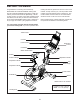
proform.com Model No. PFEX01418.0 Serial No. Write the serial number in the space above for reference. Serial Number Decal ACTIVATE YOUR WARRANTY To register your product and activate your warranty today, go to my.proform.com. CUSTOMER CARE For service at any time, go to proformservice.com. Or call 1-877-660-1168 Mon.–Fri. 6 a.m.–6 p.m. MT Sat. 8 a.m.–12 p.m. MT Please do not contact the store. CAUTION Read all precautions and instructions in this manual before using this equipment.
TABLE OF CONTENTS WARNING DECAL PLACEMENT . . . . . . . . . . . . . . . . . . . . . . . . . . . . . . . . . . . . . . . . . . . . . . . . . . . . . . . . . . . . . . .2 IMPORTANT PRECAUTIONS. . . . . . . . . . . . . . . . . . . . . . . . . . . . . . . . . . . . . . . . . . . . . . . . . . . . . . . . . . . . . . . . . . 3 BEFORE YOU BEGIN. . . . . . . . . . . . . . . . . . . . . . . . . . . . . . . . . . . . . . . . . . . . . . . . . . . . . . . . . . . . . . . . . . . . . . . .6 PART IDENTIFICATION CHART.
IMPORTANT PRECAUTIONS WARNING: To reduce the risk of burns, fire, electric shock, or injury to persons, read all important precautions and instructions in this manual and all warnings on your training bike before using your training bike. ICON assumes no responsibility for personal injury or property damage sustained by or through the use of this product. 1. It is the responsibility of the owner to ensure that all users of the training bike are adequately informed of all precautions. 8.
15. The training bike should not be used by persons weighing more than 350 lbs. (159 kg). 17. Always keep your back straight while using the training bike; do not arch your back. 18. Over exercising may result in serious injury or death. If you feel faint, if you become short of breath, or if you experience pain while exercising, stop immediately and cool down. 16. Be careful when mounting and dismounting the training bike.
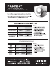
STANDARD SERVICE PLANS all 5
BEFORE YOU BEGIN Congratulations for selecting the revolutionary PROFORM® LE TOUR DE FRANCE® training bike. The LE TOUR DE FRANCE training bike is unlike any ordinary exercise bike. With full adjustability, a Wi-Fi® cycling console, an incline system that simulates actual road terrain, and an array of other innovative features, the LE TOUR DE FRANCE training bike is designed to let you enjoy the outdoor cycling experience indoors. reading this manual, please see the front cover of this manual.
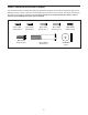
PART IDENTIFICATION CHART Use the drawings below to identify the small parts needed for assembly. The number in parentheses below each drawing is the key number of the part, from the PART LIST near the end of this manual. The number following the key number is the quantity needed for assembly. Note: If a part is not in the hardware kit, check to see if it has been preassembled. Extra parts may be included.
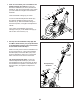
ASSEMBLY • To hire an authorized service technician to assemble the training bike, call 1-800-445-2480. • To identify small parts, see page 7. • In addition to the included tool(s), assembly requires the following tools: • Assembly requires two persons. one Phillips screwdriver • Place all parts in a cleared area and remove the packing materials. Do not dispose of the packing materials until you finish all assembly steps. Assembly may be easier if you have your own set of wrenches.
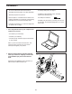
3. If there are shipping screws in the Rear Stabilizer (23), remove and discard them. 3 Attach the Rear Stabilizer (23) to the Base (1) with two M10 x 58mm Screws (74). 74 1 23 4. Using a plastic bag to keep your fingers clean, apply some of the included grease to the sides of the channel on the top of the Saddle Post (3). 4 Grease Next, orient the Saddle Post (3) so that the height indicators (B) are on the side shown.
5. Note: You can attach your own saddle to the Saddle Carriage (4) if desired. Loosen the attachment hardware (not shown) beneath the Saddle (5), and remove the Saddle. Then, attach your own saddle and retighten the attachment hardware. 5 5 Orient the Saddle Carriage (4) as shown. 91 117 Loosen the indicated Adjustment Handle (47), and slide the Saddle Carriage (4) into the Saddle Post (3). Slide the Saddle Carriage to the desired position, and tighten the Adjustment Handle.
7. Have a second person hold the Handlebar (7) near the Handlebar Carriage (105). 7 70 Locate the wire tie (D) in the right side of the Handlebar (7). Tie the indicated end of the wire tie to the Right Control Wire (81), which is marked with a tag. Then, pull the other end of the wire tie until the Right Control Wire is routed through the Handlebar. Then, untie and discard the wire tie. 7 D 105 D Route the Left Control Wire (70) through the Handlebar (7) in the same way. 81 7 D 81 8.
10. Have a second person hold the Console (9) near the Console Bracket (124). 10 9 Connect the console wires to the Ground Wire (133), the Handlebar Post Wire (68), and the Control Wires (70, 81); make sure to connect the console wire that has an “L” tag to the Control Wire that has an “L” tag, and connect the console wire that has an “R” tag to the Control Wire that has an “R” tag. 11. Insert the excess wire into the Console (9). 68 81 124 70 133 11 Tip: Avoid pinching the wires.
. Note: You can attach your own pedals if desired. 13 Identify the Right Pedal (62). Using the included flat wrench tool, firmly tighten the Right Pedal (62) clockwise into the Right Crank Arm (64). 64 Firmly tighten the Left Pedal (not shown) counterclockwise into the Left Crank Arm (not shown). IMPORTANT: You must turn the Left Pedal counterclockwise to attach it. 14. Attach the Water Bottle Holder (129) to the Frame (2) with two M4 x 10mm Screws (116). 62 14 129 116 15.
HOW TO USE THE TRAINING BIKE HOW TO PLUG IN THE POWER CORD A temporary adapter may be used to connect the power cord to a 2-pole receptacle as shown at the right if a properly grounded outlet is not available. This product must be grounded. If it should malfunction or break down, grounding provides a path of least resistance for electric current to reduce the risk of electric shock. The power cord has a plug with a grounding pin.
FEATURES OF THE TRAINING BIKE HOW TO ADJUST THE GEOMETRY OF THE TRAINING BIKE Measuring Watts The training bike can be adjusted to promote correct form and to ensure proper training of the muscles. Note: Make adjustments in small increments, and then pedal the training bike to test the adjustments. Each training bike is individually calibrated to measure your power output and allow you to monitor your watts and RPMs directly on the console.
How to Adjust the Saddle Post How to Adjust the Handlebar Post For effective training, the saddle should be at the proper height. As you pedal, there should be a slight D bend in your knees when the pedals are in the lowest posiE tion. To adjust the height of the saddle post (D), loosen the adjustment handle (E), move the saddle post upward or downward, and then retighten the adjustment handle.
HOW TO USE THE TABLET HOLDER HOW TO USE THE PEDALS IMPORTANT: The tablet holder is designed for use with most full-size tablets. Do not place any other electronic device or object in the tablet holder. To use the pedals (O), insert your shoes into the toe cages and pull the ends of the toe straps. To adjust the toe straps, press and hold the tabs on the buckles, adjust the toe straps to the desired position, and then release the tabs.
CONSOLE DIAGRAM FEATURES OF THE CONSOLE When you use the manual mode of the console, you can change the resistance of the pedals and the incline of the frame with the touch of a button. The advanced console offers an array of features designed to make your workouts more effective and enjoyable. While you exercise, the console will display continuous exercise feedback. You can even measure your heart rate using an optional heart rate monitor.
HOW TO TURN ON THE POWER HOW TO USE THE TOUCH SCREEN IMPORTANT: If the training bike has been exposed to cold temperatures, allow it to warm to room temperature before you turn on the power. If you do not do this, you may damage the console or other electrical components. The console features a tablet with a full-color touch screen. The following information will help you use the touch screen: Plug in the power cord (see HOW TO PLUG IN THE POWER CORD on page 14).
HOW TO SET UP THE CONSOLE 5. Check for firmware updates. Before you use the training bike for the first time, set up the console. First, touch the profile button, touch Settings, touch Maintenance, and then touch Update. The console will check for firmware updates. For more information, see HOW TO CHANGE CONSOLE SETTINGS on page 26. 1. Connect to your wireless network. To use iFit workouts and to use several other features of the console, the console must be connected to a wireless network.
HOW TO USE THE MANUAL MODE If desired, adjust the volume level by pressing the volume increase and decrease buttons on the console. 1. Touch the screen or press any button on the console to turn on the console. See HOW TO TURN ON THE POWER on page 19. Note: It may take a few moments for the console to be ready for use. To pause the workout, simply touch the screen or stop pedaling. To continue the workout, simply resume pedaling. 2. Select the main menu.
HOW TO USE A MAP WORKOUT OR AN ONBOARD WORKOUT To draw your own map for a workout, see HOW TO CREATE A DRAW-YOUR-OWN-MAP WORKOUT on page 24. 1. Touch the screen or press any button on the console to turn on the console. See HOW TO TURN ON THE POWER on page 19. Note: It may take a few moments for the console to be ready for use.
If the resistance level and/or incline level is too high or too low, you can manually override the setting by pressing the Resistance buttons or the Incline/ Decline buttons. If you press a Resistance button, you can then manually control the resistance level (see step 3 on page 21). If you press an Incline/Decline button, you can then manually control the incline level (see step 3 on page 21). To return to the programmed resistance and/or incline settings of the workout, touch Follow Workout.
HOW TO CREATE A DRAW-YOUR-OWN-MAP WORKOUT If you make a mistake, touch Undo on the left side of the screen. 1. Touch the screen or press any button on the console to turn on the console. The screen will display the elevation and distance statistics for your workout. See HOW TO TURN ON THE POWER on page 19. Note: It may take a few moments for the console to be ready for use. 4. Save your workout. Touch Save New Workout to save your workout.
HOW TO USE AN IFIT WORKOUT 4. Select an iFit workout that you have previously added to your schedule on iFit.com. To use an iFit workout, the console must be connected to a wireless network (see HOW TO CONNECT TO A WIRELESS NETWORK on page 27). An iFit account is also required. IMPORTANT: Before iFit workouts will load, you must add them to your schedule on iFit.com (see step 1). 1. Add workouts to your schedule on iFit.com. To load an iFit workout from iFit.
HOW TO CHANGE CONSOLE SETTINGS 3. View the console tour presentation. IMPORTANT: Some of the settings and features described may not be enabled. Occasionally, a firmware update may cause your console to function slightly differently. To view a tour presentation that will guide you through the features of the console, touch How It Works. 1. Select the settings main menu. 4. Customize the unit of measurement and other settings. First, turn on the power (see HOW TO TURN ON THE POWER on page 19).
7. Calibrate the incline system. 3. Enable Wi-Fi. To calibrate the incline system, touch Maintenance, touch Calibrate Incline, and then touch Begin. The frame will automatically rise to the maximum incline level, lower to the minimum incline level, and then return to the starting position. This will calibrate the incline system. When the incline system is calibrated, touch Finish. Make sure that Wi-Fi® is enabled. If it is not enabled, touch the Wi-Fi toggle to enable it. 4.
HOW TO USE THE SOUND SYSTEM THE OPTIONAL CHEST HEART RATE MONITOR To play music or audio books through the console sound system while you exercise, plug a 3.5 mm male to 3.5 mm male audio cable (not included) into the jack on the console and into a jack on your personal audio player; make sure that the audio cable is fully plugged in. Note: To purchase an audio cable, see your local electronics store.
FCC INFORMATION This equipment has been tested and found to comply with the limits for a Class B digital device, pursuant to part 15 of the FCC Rules. These limits are designed to provide reasonable protection against harmful interference in a residential installation. This equipment generates, uses, and can radiate radio frequency energy and, if not installed and used in accordance with the instructions, may cause harmful interference to radio communications.
MAINTENANCE AND TROUBLESHOOTING HOW TO MAINTAIN THE TRAINING BIKE reset button inside the opening, and have a second person plug in the power adapter. Continue holding the reset button until the console turns on. When the reset operation is complete, the console will turn off and then turn back on. If it does not, press the power switch off and then on again. Once the console turns on, check for firmware updates (see step 5 on page 20). Note: It may take a few minutes for the console to be ready for use.
HOW TO ADJUST THE DRIVE BELT If the pedals slip while you are pedaling, the drive belt may need to be adjusted. 12 To adjust the drive belt, first press the power switch to the off position and unplug the power cord. Next, locate the access hole in the underside of the Right Shield (12). Using a hex key, tighten the Idler Adjustment Screw (39) until the drive belt (not shown) is tight.
EXERCISE GUIDELINES Aerobic Exercise—If your goal is to strengthen your cardiovascular system, you must perform aerobic exercise, which is activity that requires large amounts of oxygen for prolonged periods of time. For aerobic exercise, adjust the intensity of your exercise until your heart rate is near the highest number in your training zone. WARNING: Before beginning this or any exercise program, consult your physician.
PART LIST Key No. Qty. 1 2 3 4 5 6 7 8 9 10 11 12 13 14 15 16 17 18 19 20 21 22 23 24 25 26 27 28 29 30 31 32 33 34 35 36 37 38 39 40 41 42 43 44 45 46 47 48 49 50 1 1 1 1 1 1 1 1 1 1 1 1 2 1 1 1 1 1 1 2 2 1 1 4 2 3 2 1 2 1 1 1 1 1 1 1 1 1 1 1 1 1 1 1 1 1 3 1 1 1 Model No. PFEX01418.0 R1118A Description Key No. Qty.
Key No. Qty. 101 102 103 104 105 106 107 108 109 110 111 112 113 114 115 116 117 118 119 120 1 1 10 7 1 5 1 1 10 4 4 1 6 5 2 4 4 5 1 1 Description Key No. Qty.
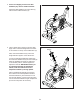
71 13 106 106 35 42 40 130 11 82 41 95 94 43 44 82 45 32 54 5 85 14 71 88 85 3 31 91 92 136 39 96 117 136 87 30 38 86 80 89 67 51 89 114 101 58 78 57 47 34 99 102 95 86 103 49 48 36 47 59 4 71 37 97 16 54 95 33 15 109 91 92 29 117 109 63 68 107 97 113 56 61 108 10 83 97 35 17 66 97 55 8 47 6 46 72 18 12 116 90 113 112 74 1 20 19 75 7 94 25 13 117 95 122 104 125 123 104 95 109 64 72 24 79 21 29 62 73 26
ORDERING REPLACEMENT PARTS To order replacement parts, please see the front cover of this manual.