www.proform.com Model No. PFEX01915.0 Serial No. Write the serial number in the space above for reference. Serial Number Decal ACTIVATE YOUR WARRANTY To register your product and activate your warranty today, go to www.proformservice.com/ registration. CUSTOMER CARE For service at any time, go to www.proformservice.com. Or call 1-877-660-1168 Mon.–Fri. 6 a.m.–6 p.m. MT Sat. 8 a.m.–12 p.m. MT Please do not contact the store.
TABLE OF CONTENTS WARNING DECAL PLACEMENT . . . . . . . . . . . . . . . . . . . . . . . . . . . . . . . . . . . . . . . . . . . . . . . . . . . . . . . . . . . . . . .2 IMPORTANT PRECAUTIONS . . . . . . . . . . . . . . . . . . . . . . . . . . . . . . . . . . . . . . . . . . . . . . . . . . . . . . . . . . . . . . . . . . 3 BEFORE YOU BEGIN. . . . . . . . . . . . . . . . . . . . . . . . . . . . . . . . . . . . . . . . . . . . . . . . . . . . . . . . . . . . . . . . . . . . . . . .
IMPORTANT PRECAUTIONS WARNING: To reduce the risk of burns, fire, electric shock, or injury to persons, read all important precautions and instructions in this manual and all warnings on your training bike before using your training bike. ICON assumes no responsibility for personal injury or property damage sustained by or through the use of this product. 1. It is the responsibility of the owner to ensure that all users of the training bike are adequately informed of all precautions. 10.
STANDARD SERVICE PLANS all 5
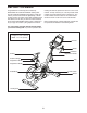
BEFORE YOU BEGIN Congratulations for selecting the revolutionary PROFORM® LE TOUR DE FRANCE® training bike. The LE TOUR DE FRANCE training bike is unlike any ordinary exercise bike. With full adjustability, a Wi-Fi® cycling console, an incline system that simulates actual road terrain, and an array of other innovative features, the LE TOUR DE FRANCE training bike is designed to let you enjoy the outdoor cycling experience indoors. reading this manual, please see the front cover of this manual.
PART IDENTIFICATION CHART Use the drawings below to identify the small parts needed for assembly. The number in parentheses below each drawing is the key number of the part, from the PART LIST near the end of this manual. The number following the key number is the quantity needed for assembly. Note: If a part is not in the hardware kit, check to see if it has been preassembled. Extra parts may be included.
ASSEMBLY • To hire an authorized service technician to assemble the training bike, call 1-800-445-2480. • To identify small parts, see page 7. • In addition to the included tool(s), assembly requires the following tools: • Assembly requires two persons. one Phillips screwdriver • Place all parts in a cleared area and remove the packing materials. Do not dispose of the packing materials until you finish all assembly steps. Assembly may be easier if you have your own set of wrenches.
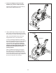
3. If there are shipping screws in the Rear Stabilizer (23), remove and discard them. 3 Attach the Rear Stabilizer (23) to the Base (1) with two M10 x 58mm Screws (74). 74 1 23 4. Using a plastic bag to keep your fingers clean, apply some of the included grease to the sides of the channel on the top of the Saddle Post (3). 4 Grease Next, orient the Saddle Post (3) so that the height indicators are on the side shown.
5. Note: You can attach your own saddle to the Saddle Carriage (4) if desired. Loosen the attachment hardware (not shown) beneath the Saddle (5), and remove the Saddle. Then, attach your own saddle and retighten the attachment hardware. 5 5 4 Orient the Saddle Carriage (4) as shown. 91 3 54 117 Loosen the Adjustment Handle (47), and slide the Saddle Carriage (4) into the Saddle Post (3). Slide the Saddle Carriage to the desired position, and tighten the Adjustment Handle.
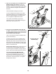
7. Have a second person hold the Handlebar (7) near the Handlebar Carriage (105). 7 7 Locate one of the remaining wire ties in the Handlebar Carriage (105). Tie the indicated end of the wire tie to the Right Extension Wire (107). Then, pull the other end of the wire tie until the Right Extension Wire is routed through the Handlebar Carriage. Then, untie and discard the wire tie. 108 107 Wire Tie 105 Route the Left Extension Wire (108) through the Handlebar Carriage (105) in the same way. 8.
10. Tip: Avoid pinching the wires. Attach the Console (9) to the Handlebar Carriage (105) with four M4 x 12mm Screws (111); start all four Screws, and then tighten them. 10 9 105 111 Avoid pinching the wires 11. Attach the Tray (8) to the Frame (2) with two M4 x 10mm Screws (116). 11 2 8 116 12. Note: You can attach your own pedals if desired. 12 Identify the Right Pedal (62). Using the included flat wrench tool, firmly tighten the Right Pedal (62) clockwise into the Right Crank Arm (64).
HOW TO USE THE TRAINING BIKE HOW TO PLUG IN THE POWER CORD A temporary adapter may be used to connect the power cord to a 2-pole receptacle as shown at the right if a properly grounded outlet is not available. This product must be grounded. If it should malfunction or break down, grounding provides a path of least resistance for electric current to reduce the risk of electric shock. The power cord has a plug with a grounding pin.
FEATURES OF THE TRAINING BIKE HOW TO ADJUST THE GEOMETRY OF THE TRAINING BIKE Measuring Watts The training bike can be adjusted to match the geometry of your road bike to promote correct form and to ensure proper training of the muscles. Note: Make adjustments in small increments, and then pedal the training bike to test the adjustments. Each training bike is individually calibrated to measure your power output and allow you to monitor your watts and RPMs directly on the console.
How to Adjust the Saddle Post HOW TO LEVEL THE TRAINING BIKE For effective training, the saddle should be at the proper height. As Saddle you pedal, there Post should be a slight bend in your knees when the pedals are Handle in the lowest position. To adjust the height of the saddle post, loosen the adjustment handle, move the saddle post upward or downward, and then retighten the adjustment handle.
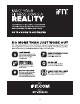
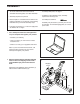
CONSOLE DIAGRAM MAKE YOUR FITNESS GOALS A REALITY WITH IFIT.COM Upload your workout results to the iFit cloud and track your accomplishments. With your new iFit-compatible fitness equipment, you can use an array of features on iFit.com to make your fitness goals a reality: Set calorie, time, distance, or watts goals for your workouts. Train anywhere in the world with customizable Google Maps™. Watch high-definition videos with simulated workouts.
FEATURES OF THE CONSOLE HOW TO TURN ON THE POWER The advanced console offers an array of features designed to make your workouts more effective and enjoyable. IMPORTANT: If the training bike has been exposed to cold temperatures, allow it to warm to room temperature before you turn on the power. If you do not do this, you may damage the console displays or other electrical components.
HOW TO USE THE TOUCH SCREEN 2. Check for firmware updates. The console features a tablet with a full-color touch screen. The following information will help you become familiar with the tablet’s advanced technology: First, see step 1 on page 24 and step 2 on page 26 and select the maintenance mode. Then, see step 3 on page 26 and check for firmware updates. • The console functions similarly to other tablets.
HOW TO USE THE MANUAL MODE Change gears by pressing the buttons on the shifters. Note: After you press a button, it will take a moment for the training bike to change to the selected gear. To avoid damaging the shifters, do not pull on the shifters or squeeze the shifters. 1. Touch the screen or begin pedaling to activate the console. See HOW TO TURN ON THE POWER on page 17. Press the buttons on the left shifter to change the front gear; press the buttons on the right shifter to change the rear gear. 2.
6. Do intervals if desired. 7. Wear a heart rate monitor and measure your heart rate if desired. During a workout, you can use the interval screen to measure your performance for short periods of time. To select the interval screen, simply flick or slide the screen. You can wear an optional heart rate monitor to measure your heart rate. For more information about the optional heart rate monitor, see page 28. Note: The console is compatible with BLUETOOTH® Smart heart rate monitors.
HOW TO USE A LE TOUR DE FRANCE WORKOUT At the end of the first segment of the workout, the incline will automatically adjust to the incline level for the next segment. 1. Touch the screen or begin pedaling to activate the console. When the incline changes, the resistance of the pedals will also change. To maintain a steady pedaling cadence, change gears by pressing the buttons on the shifters. See HOW TO TURN ON THE POWER on page 17. 2. Select the main menu.
HOW TO USE A SET-A-GOAL WORKOUT The workout will continue until you reach the goal that you set. A workout summary will appear on the screen. After you view the workout summary, touch the Finish button to return to the main menu. You may also be able to either save or publish your results using one of the options on the screen. 1. Touch the screen or begin pedaling to activate the console. See HOW TO TURN ON THE POWER on page 17.
HOW TO USE AN IFIT WORKOUT When you select an iFit workout, the screen will show the name, the estimated duration, and the distance of the workout. The screen will also show the approximate number of calories you will burn during the workout. If you select a competition workout, the display will count down to the beginning of the race. Note: To use an iFit workout, you must have access to a wireless network (see HOW TO USE THE WIRELESS NETWORK MODE on page 27). An iFit account is also required. 1.
HOW TO USE THE EQUIPMENT SETTINGS MODE 6. Select a time for the cadence timeout. IMPORTANT: Some of the features described may not be enabled. Occasionally, a firmware update may cause your console to function slightly differently. The console features a cadence timeout feature; if no buttons are touched or pressed and the pedals do not move for a set amount of time, the console will prompt you to resume or end the workout. 1. Select the settings main menu.
9. Hide or display the gears button. 12. Enable or disable street view. The console features an option to hide the gears button to prevent unauthorized users from accessing the settings main menu. During some workouts, the screen may show a map. To enable or disable the street view feature of the maps, first touch the Street View button. Next, touch the Enable checkbox or the Disable checkbox. Then, touch the back button on the screen.
HOW TO USE THE MAINTENANCE MODE Note: Occasionally, a firmware update may cause your console to function slightly differently. These updates are always designed to improve your training experience. IMPORTANT: Some of the features described may not be enabled. Occasionally, a firmware update may cause your console to function slightly differently. 4. Calibrate the incline system of the training bike. 1. Select the settings main menu. Touch the Calibrate Incline button.
HOW TO USE THE WIRELESS NETWORK MODE When a list of networks appears, touch the desired network. Note: You will need to know your network name (SSID). If your network has a password, you will also need to know the password. The console features a wireless network mode that allows you to set up a wireless network connection. Note: You must have your own wireless network and an 802.11b/g router with SSID broadcast enabled (hidden networks are not supported).
HOW TO USE THE SOUND SYSTEM To use the keyboard, see HOW TO USE THE TOUCH SCREEN on page 18. To play music or audio books through the console sound system while you exercise, plug a 3.5 mm male to 3.5 mm male audio cable (not included) into the jack on the console and into a jack on your MP3 player, CD player, or other personal audio player; make sure that the audio cable is fully plugged in. Note: To purchase an audio cable, see your local electronics store.
FCC INFORMATION This equipment has been tested and found to comply with the limits for a Class B digital device, pursuant to part 15 of the FCC Rules. These limits are designed to provide reasonable protection against harmful interference in a residential installation. This equipment generates, uses, and can radiate radio frequency energy and, if not installed and used in accordance with the instructions, may cause harmful interference to radio communications.
MAINTENANCE AND TROUBLESHOOTING HOW TO MAINTAIN THE TRAINING BIKE HOW TO ADJUST THE DRIVE BELT Regular maintenance is important for optimal performance and to reduce wear. Inspect and properly tighten all parts each time the training bike is used. Replace any worn parts immediately. If the pedals slip while you are pedaling, the drive belt may need to be adjusted. To adjust the drive belt, first press the power switch to the off position and unplug the power cord.
EXERCISE GUIDELINES Aerobic Exercise—If your goal is to strengthen your cardiovascular system, you must perform aerobic exercise, which is activity that requires large amounts of oxygen for prolonged periods of time. For aerobic exercise, adjust the intensity of your exercise until your heart rate is near the highest number in your training zone. WARNING: Before beginning this or any exercise program, consult your physician.
SUGGESTED STRETCHES The correct form for several basic stretches is shown at the right. Move slowly as you stretch; never bounce. 1. Toe Touch Stretch Stand with your knees bent slightly and slowly bend forward from your hips. Allow your back and shoulders to relax as you reach down toward your toes as far as possible. Hold for 15 counts, then relax. Repeat 3 times. Stretches: Hamstrings, back of knees and back. 1 2. Hamstring Stretch Sit with one leg extended.
PART LIST Key No. Qty. 1 2 3 4 5 6 7 8 9 10 11 12 13 14 15 16 17 18 19 20 21 22 23 24 25 26 27 28 29 30 31 32 33 34 35 36 37 38 39 40 41 42 43 44 45 46 47 48 49 50 1 1 1 1 1 1 1 1 1 1 1 1 2 1 1 1 1 1 1 2 2 1 1 4 2 2 2 1 2 1 1 1 1 1 1 1 1 1 1 1 1 1 1 1 1 1 3 1 1 1 Model No. PFEX01915.0 R0615A Description Key No. Qty.
Key No. Qty. 101 102 103 104 105 106 107 108 109 110 111 112 113 1 1 10 5 1 5 1 1 10 4 4 1 2 Description Key No. Qty.
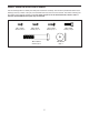
71 13 106 106 97 35 42 40 113 56 61 108 92 11 82 41 109 94 43 82 44 33 67 47 71 14 37 85 95 87 30 38 86 89 51 35 101 96 89 114 117 78 57 47 99 39 34 102 88 86 103 3 31 91 92 58 54 5 49 48 36 59 4 85 32 71 45 97 16 54 95 95 15 109 91 63 29 117 68 107 10 83 8 66 17 59 104 2 78 97 47 69 50 111 57 97 80 93 52 98 9 53 55 90 113 74 112 116 13 25 72 94 118 23 65 28 46 18 6 115 105 73 95 100 65 21 54 12 24
ORDERING REPLACEMENT PARTS To order replacement parts, please see the front cover of this manual.