
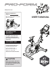
Instructions / Assembly

10
5
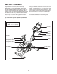
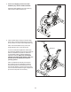
5. Note: You can attach your own saddle to the
Saddle Carriage (4) if desired. Loosen the
attachment hardware (not shown) beneath the
Saddle (5), and remove the Saddle. Then, attach
your own saddle and retighten the attachment
hardware.
Orient the Saddle Carriage (4) as shown.
Loosen the Adjustment Handle (47), and slide
the Saddle Carriage (4) into the Saddle Post (3).
Slide the Saddle Carriage to the desired posi-
tion, and tighten the Adjustment Handle.
Then, attach an M4 Washer (54) and the
Carriage Cover (91) to the Saddle Carriage (4)
with an M4 x 14mm Screw (117).
3
4
5
117
47
54
91
6
6
2
68
105
47
Wire
Tie
Wire Tie
Access
Hole
Pull Here
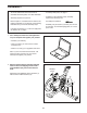
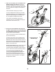
6. See step 8. If the Handlebar Clamp (28) and
four M6 x 16mm Screws (110) are preattached
to the Handlebar Carriage (105), remove them
and set them aside until step 8.
Have a second person hold the Handlebar Post
(6) near the Frame (2).
Locate the long wire tie in the Handlebar Post
(6). Tie the lower end of the long wire tie to the
Main Wire (68). Next, locate the same wire tie in
the access hole in the Handlebar Carriage (105).
Pull the wire tie upward until the end of the Main
Wire is in the access hole.
See the inset drawing. Next, pull the upper end
of the long wire tie until the Main Wire (68) is
routed through the Handlebar Carriage (105) as
shown. Then, untie and discard the long wire tie.
Tip: Avoid pinching the Main Wire (68).
Loosen the indicated Adjustment Handle (47),
and insert the Handlebar Post (6) into the
Frame (2). Move the Handlebar Post upward or
downward to the desired position, and tighten
the Adjustment Handle.
Avoid pinching the
Main Wire (68)
105
68
Wire
Tie