
User's Manual

7
3
4
6
Adjustment
H
oles
1
23
24
75
72
26
91
6
27
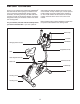
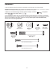
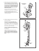
3. Loosen the Adjustment Knob (27) in the Frame
(1) a few turns.
O
rient the Seat Post (6) as shown. Then, pull
the Adjustment Knob (27) outward and insert
t
he Seat Post into the Frame (1).
Slide the Seat Post (6) upward or downward to
the desired position, and release the
Adjustment Knob (27).
Move the Seat Post (6) upward or downward
slightly to make sure that the Adjustment
Knob (27) is engaged in one of the adjust-
ment holes in the Seat Post. Then, tighten the
Adjustment Knob.
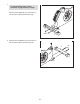
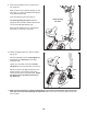
4. Orient the Seat (23) and the Seat Carriage (24)
as shown.
Attach the Seat (23) to the Seat Carriage (24)
with four M8 Locknuts (72) and four M8 Split
Washers (75).
Slide the Seat Carriage (24) onto the Seat Post
(6). Then, slide the Seat Carriage all the way
forward and tighten the Seat Adjustment Knob
(26).
Attach an M4 x 5mm Bright Screw (91) to the
rear of the Seat Post (6).