proform.com Model No. PFEX11916.2 Serial No. Write the serial number in the space above for reference. Serial Number Decal ACTIVATE YOUR WARRANTY To register your product and activate your warranty today, go to my.proform.com. CUSTOMER CARE For service at any time, go to proformservice.com. Or call 1-888-533-1333 Mon.–Fri. 6 a.m.–6 p.m. MT Sat. 8 a.m.–12 p.m. MT Please do not contact the store. CAUTION Read all precautions and instructions in this manual before using this equipment.
TABLE OF CONTENTS WARNING DECAL PLACEMENT . . . . . . . . . . . . . . . . . . . . . . . . . . . . . . . . . . . . . . . . . . . . . . . . . . . . . . . . . . . . . . .2 IMPORTANT PRECAUTIONS. . . . . . . . . . . . . . . . . . . . . . . . . . . . . . . . . . . . . . . . . . . . . . . . . . . . . . . . . . . . . . . . . . 3 BEFORE YOU BEGIN. . . . . . . . . . . . . . . . . . . . . . . . . . . . . . . . . . . . . . . . . . . . . . . . . . . . . . . . . . . . . . . . . . . . . . . .5 PART IDENTIFICATION CHART.
IMPORTANT PRECAUTIONS WARNING: To reduce the risk of serious injury, read all important precautions and instructions in this manual and all warnings on your exercise bike before using your exercise bike. ICON assumes no responsibility for personal injury or property damage sustained by or through the use of this product. 1. It is the responsibility of the owner to ensure that all users of the exercise bike are adequately informed of all precautions. 9.
STANDARD SERVICE PLANS 4
BEFORE YOU BEGIN Thank you for selecting the new PROFORM® X-BIKE DUO exercise bike. Cycling is an effective exercise for increasing cardiovascular fitness, building endurance, and toning the body. The X-BIKE DUO exercise bike provides a selection of features designed to make your workouts at home more effective and enjoyable. reading this manual, please see the front cover of this manual. To help us assist you, note the product model number and serial number before contacting us.
PART IDENTIFICATION CHART Use the drawings below to identify the small parts needed for assembly. The number in parentheses below each drawing is the key number of the part, from the PART LIST near the end of this manual. The number following the key number is the quantity needed for assembly. Note: If a part is not in the hardware kit, check to see if it has been preassembled. Extra parts may be included.
ASSEMBLY • To hire an authorized service technician to assemble this product, call 1-800-445-2480. • To identify small parts, see page 6. • In addition to the included tool(s), assembly requires the following tool(s): • Assembly requires two persons. • Place all parts in a cleared area and remove the packing materials. Do not dispose of the packing materials until you finish all assembly steps. one Phillips screwdriver • Left parts are marked “L” or “Left” and right parts are marked “R” or “Right.
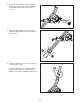
3. Identify the Front Stabilizer (3) and attach it to the Frame (1) with two M8 x 60mm Bolts (75) and two M8 Locknuts (67) (only one side is shown). 3 3 67 4. Attach the Rear Stabilizer (4) to the Upright (2) with two M8 x 60mm Bolts (75) and two M8 Locknuts (67). 1 4 67 4 2 75 5. Orient the Handlebar (5) so that the screw (A) is in the indicated location. 5 Attach the Handlebar (5) to the Upright (2) with two M8 x 60mm Bolts (75), two M8 x 16mm Washers (71), and two Handlebar Clamps (48).
6. Orient the Seat Frame (8) near the Seat Post (7) as shown. Pull the Pin Knob (20) outward and slide the Seat Frame onto the Seat Post. 6 70 Next, insert the Seat Axle (57) through the Seat Frame (8) and the Seat Post (7). Then, tighten an M8 x 16mm Screw (70) with an M8 x 25mm Washer (72) into each end of the Seat Axle at the same time. 72 57 8 70 20 72 7 7. Attach the Seat Bracket (9) to the Seat Frame (8) with three M8 x 16mm Screws (70); start all the Screws, and then tighten them.
9. Attach the Backrest (11) to the Seat Bracket (9) with two M6 x 40mm Screws (77). 9 11 9 77 10. The Console (6) can use four D batteries (not included); alkaline batteries are recommended. Do not use old and new batteries together or alkaline, standard, and rechargeable batteries together. IMPORTANT: If the Console has been exposed to cold temperatures, allow it to warm to room temperature before you insert batteries. Otherwise, you may damage the displays or other electronic components.
12. Identify the Right Pedal (55). 12 Using an adjustable wrench, firmly tighten the Right Pedal (55) clockwise into the Right Crank Arm (18). 56 Firmly tighten the Left Pedal (56) counterclockwise into the Left Crank Arm (not shown). IMPORTANT: You must turn the Left Pedal counterclockwise to attach it. Then, adjust the right strap (E) to the desired position, and press the ends of the strap onto the tabs (F) on the Right Pedal (55). Adjust the strap on the Left Pedal (56) in the same way. 13.
HOW TO USE THE EXERCISE BIKE HOW TO USE THE UPRIGHT POSITION Adjust the Seat Frame (8) to the upright position. Pull the Seat Frame Pin (33) outward, move the Seat Frame to the 33 8 7 position shown, and release the Seat Frame Pin into an adjustment hole in the end of the Seat Post (7); make sure that the Seat Frame Pin is securely engaged. Move the Frame (1) to the upright position. Place your foot on the Rear Stabilizer (4) and hold the Seat Frame (8) with one hand in the indicated location.
HOW TO USE THE RECUMBENT POSITION Adjust the Seat Frame (8) to the recumbent position. Pull the Seat Frame Pin (33) outward, move the Seat Frame to the recumbent posi7 33 8 tion, and release the Seat Frame Pin into an adjustment hole in the end of the Seat Post (7); make sure that the Seat Frame Pin is securely engaged. Move the Frame (1) to the recumbent position. Place your foot on the Rear Stabilizer (4) and hold the Seat Frame (8) with one hand in the indicated location.
HOW TO USE THE STORAGE POSITION See the drawing at the left. Next, pull upward on the Seat Frame (8) and pull the Frame Pin (13) outward with your other hand. Then, move the Upright (2) upward until the exercise bike is in the storage position, and release the Frame Pin into the hole in the Frame (1); make sure that the Frame Pin is securely engaged in the Frame. When the exercise bike is not in use, it can be moved to a compact storage position. Adjust the Seat Frame (8) to the storage position.
CONSOLE DIAGRAM FEATURES OF THE CONSOLE The console also offers a selection of preset workouts. Each preset workout automatically changes the resistance of the pedals and prompts you to maintain a target speed as it guides you through an effective workout. IMPORTANT: To activate your console and begin using its exclusive features, see assembly step 13 on page 11. To use the manual mode, see page 16. To use a preset workout, see page 17. To connect your tablet to the console, see page 18.
HOW TO USE THE MANUAL MODE The upper display—This display will show your pedaling speed in revolutions per minute (RPM) and your power output in watts. The display will change every few seconds. 1. Turn on the console. Press any button or begin pedaling to turn on the console. When you turn on the console, the displays will turn on and the console will be ready for use. This display will also show the resistance level of the pedals for a few seconds each time the resistance level changes. 2.
To pause the console, stop pedaling. When the console is paused, the displays will pause. To continue your workout, simply resume pedaling. HOW TO USE A PRESET WORKOUT To reset the displays to zero, press the On/Reset button. Press any button or begin pedaling to turn on the console. Note: The console can show pedaling speed and distance in either miles or kilometers. To change the unit of measurement, see THE SETTINGS MODE on page 19.
THE OPTIONAL CHEST HEART RATE MONITOR As you exercise, keep your pedaling speed within the target speed zone for the current segment by increasing or decreasing your pedaling speed or by increasing or decreasing the resistance of the pedals. If the resistance level for the current segment is too high or too low, you can manually override the setting by pressing the Digital Resistance buttons.
3. Connect your tablet to the console. THE SETTINGS MODE Press the iFit Sync button on the console; the console pairing number will appear in the display. Then, follow the instructions in the iFit Bluetooth Tablet app to connect your tablet to the console. The console features a settings mode that allows you to select a unit of measurement for the console and to view console usage information.
MAINTENANCE AND TROUBLESHOOTING MAINTENANCE then carefully pull the Right Shield away from the exercise bike. Regular maintenance is important for optimal performance and to reduce wear. Inspect and properly tighten all parts each time the exercise bike is used. Replace any worn parts immediately. Note: For clarity, the right shield is not shown in the drawing below. Locate the Reed Switch (29). Rotate the Right Crank Arm (18) until a Magnet (90) is aligned with the Reed Switch.
EXERCISE GUIDELINES Burning Fat—To burn fat effectively, you must exercise at a low intensity level for a sustained period of time. During the first few minutes of exercise, your body uses carbohydrate calories for energy. Only after the first few minutes of exercise does your body begin to use stored fat calories for energy. If your goal is to burn fat, adjust the intensity of your exercise until your heart rate is near the lowest number in your training zone.
PART LIST Key No. Qty. 1 2 3 4 5 6 7 8 9 10 11 12 13 14 15 16 17 18 19 20 21 22 23 24 25 26 27 28 29 30 31 32 33 34 35 36 37 38 39 40 41 42 43 44 45 46 1 1 1 1 1 1 1 1 1 1 1 1 1 1 1 1 1 1 1 2 1 1 1 1 1 1 1 2 1 1 1 1 1 2 1 1 4 2 2 1 2 1 1 1 1 2 Model No. PFEX11916.2 R1217A Description Key No. Qty.
39 20 70 70 77 72 77 36 70 39 78 8 9 11 7 10 61 80 50 56 80 35 34 63 70 85 81 81 72 17 57 33 81 19 75 37 79 16 67 76 82 4 54 13 79 68 67 88 34 14 47 74 2 86 87 54 84 22 80 62 1 32 27 31 74 28 6 5 53 23 41 21 65 82 76 67 24 12 25 44 43 29 51 79 81 79 68 20 81 18 61 81 75 66 46 50 59 60 64 55 3 81 15 45 42 52 60 64 89 28 81 59 69 26 66 58 40 90 69 83 37 49 73 75 48 41 30 79 48 75 71 38 EXPLOD
ORDERING REPLACEMENT PARTS To order replacement parts, please see the front cover of this manual.