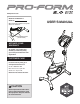
www.proform.com Model No. PFEX51912.2 Serial No. Write the serial number in the space above for reference. Serial Number Decal (under frame) ACTIVATE YOUR WARRANTY To register your product and activate your warranty today, go to www.proformservice.com/ registration. CUSTOMER CARE For service at any time, go to www.proformservice.com. Or call 1-888-533-1333 Mon.–Fri. 6 a.m.–6 p.m. MT Sat. 8 a.m.–12 p.m. MT Please do not contact the store.
TABLE OF CONTENTS WARNING DECAL PLACEMENT . . . . . . . . . . . . . . . . . . . . . . . . . . . . . . . . . . . . . . . . . . . . . . . . . . . . . . . . . . . . . . .2 IMPORTANT PRECAUTIONS . . . . . . . . . . . . . . . . . . . . . . . . . . . . . . . . . . . . . . . . . . . . . . . . . . . . . . . . . . . . . . . . . . 3 BEFORE YOU BEGIN. . . . . . . . . . . . . . . . . . . . . . . . . . . . . . . . . . . . . . . . . . . . . . . . . . . . . . . . . . . . . . . . . . . . . . . .
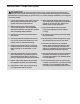
IMPORTANT PRECAUTIONS WARNING: To reduce the risk of serious injury, read all important precautions and instructions in this manual and all warnings on your exercise bike before using your exercise bike. ICON assumes no responsibility for personal injury or property damage sustained by or through the use of this product. 1. It is the responsibility of the owner to ensure that all users of the exercise bike are adequately informed of all precautions. 9.
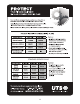
STANDARD SERVICE PLANS 4
BEFORE YOU BEGIN Thank you for selecting the new PROFORM® 2.0 ES exercise bike. Cycling is an effective exercise for increasing cardiovascular fitness, building endurance, and toning the body. The 2.0 ES exercise bike provides a selection of features designed to make your workouts at home more effective and enjoyable. reading this manual, please see the front cover of this manual. To help us assist you, note the product model number and serial number before contacting us.
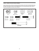
PART IDENTIFICATION CHART Use the drawings below to identify the small parts needed for assembly. The number in parentheses below each drawing is the key number of the part, from the PART LIST near the end of this manual. The number following the key number is the quantity needed for assembly. Note: If a part is not in the hardware kit, check to see if it has been preassembled. Extra parts may be included.
ASSEMBLY • To hire an authorized service technician to assemble this product, call 1-800-445-2480. • To identify small parts, see page 6. • In addition to the included tool(s), assembly requires the following tools: • Assembly requires two persons. one Phillips screwdriver • Place all parts in a cleared area and remove the packing materials. Do not dispose of the packing materials until you finish all assembly steps. one adjustable wrench Assembly may be easier if you have your own set of wrenches.
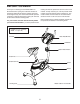
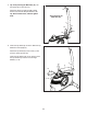
3. Orient the Front Stabilizer (2) as indicated by the sticker. 3 While a second person lifts the front of the Frame (1), attach the Front Stabilizer (2) to the Frame with two M10 x 80mm Screws (36). 36 2 1 4. Orient the Upright (3) as shown. Have a second person hold the Upright near the Frame (1). 4 Locate the wire tie in the lower end of the Upright (3). Tie the wire tie to the Main Wire (31). Then, pull the upper end of the wire tie until the Main Wire is routed through the Upright.
5. Tip: Avoid pinching the Main Wire (31). Set the Upright (3) on the Frame (1). 5 31 Attach the Upright (3) with four M8 x 25mm Screws (44) and four M8 Split Washers (45). Tip: Start all the Screws, and then tighten them. Avoid pinching the Main Wire (31) 3 44 44 45 45 1 6. Orient the Top Shield (9) as shown. Slide the Top Shield onto the Upright (3). 6 Attach the Top Shield (9) to the Frame (1) with two M4 x 16mm Screws (40). Orient the Top Shield Cap (10) as shown.
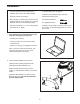
7. Orient the Seat (12) and the Seat Carriage (30) as shown. Attach the Seat to the Seat Carriage with four M8 Locknuts (37), four M8 Split Washers (45), and four M8 Washers (56). Note: The Locknuts, Split Washers, and Washers may be preattached to the Seat. 7 12 30 56 56 45 8. Loosen and remove the Seat Knob (11) from the Seat Carriage (30). 8 Look underneath the Seat (12), and locate the Carriage Block (55) inside the Seat Carriage (30). 45 37 37 12 55 Orient the Seat Post (5) as shown.
9. Loosen and remove the Seat Post Knob (48) from the Frame (1). 9 Next, insert the Seat Post (5) into the Frame (1), and press the Seat Post Bushing (20) downward into the Frame. Slide the Seat Post (5) upward or downward to the desired position, and then insert the Seat Post Knob (48) into the Frame (1) and into one of the adjustment holes in the Seat Post. Then, tighten the Seat Post Knob. Adjustment Holes 20 5 1 48 10. Unite and discard the wire tie on the Main Wire (31).
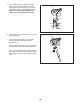
11. Have a second person hold the Handlebar (47) near the Upright (3). 11 Locate the Pulse Wire (52) in the Handlebar (47). Insert the Pulse Wire into the large hole in the Upright (3), and then pull the Pulse Wire out of the top of the Console Plate (19). 19 47 Attach the Handlebar (47) and the Console Plate (19) to the Upright (3) with two M8 x 25mm Screws (44) and two M8 Curved Washers (8). 52 8 44 12. The Console (6) can use four D batteries (not included); alkaline batteries are recommended.
. While a second person holds the Console (6) near the Console Plate (19), connect the wires on the Console to the Main Wire (31) and to the Pulse Wire (52). 13 6 Insert the excess wire into the Console Plate (19) or into the Console (6). 31 Tip: Avoid pinching the wires. Attach the Console (6) to the Console Plate (19) with four M4 x 16mm Screws (40). Tip: Start all the Screws, and then tighten them. 19 52 Avoid pinching the wires 14.
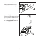
15. Identify the Right Pedal (26). Using an adjustable wrench, firmly tighten the Right Pedal clockwise into the right arm of the Crank (13). 15 Tighten the Left Pedal (not shown) counterclockwise into the left arm of the Crank (not shown). 13 Adjust the strap on the Right Pedal (26) to the desired position, and press the end of the strap onto the tab on the Right Pedal. Adjust the strap on the Left Pedal (not shown) in the same way. Strap 26 Tab 16.
HOW TO USE THE EXERCISE BIKE HOW TO LEVEL THE EXERCISE BIKE HOW TO ADJUST THE SEAT POST If the exercise bike rocks slightly on your floor during use, turn one or both of the leveling feet on the rear stabilizer until the rocking motion is eliminated. For effective exercise, the seat should be at the proper height. As you pedal, there should be a slight bend in your knees when the pedals are in the lowest position. To adjust the seat post, first remove the seat post knob from the frame.
CONSOLE DIAGRAM FEATURES OF THE CONSOLE You can even connect your MP3 player or CD player to the console sound system and listen to your favorite music or audio books while you exercise. The advanced console offers an array of features designed to make your workouts more effective and enjoyable. To use the manual mode, see page 17. To use a preset workout, see page 19. To use the settings mode, see page 20. To use the sound system, see page 20.
HOW TO USE THE MANUAL MODE Profile—When a workout is selected, this display mode will show a profile of the resistance settings of the workout. 1. Turn on the console. Pulse—This display mode will show your heart rate when you use the handgrip heart rate monitor (see step 5 on page 18). Press any button or begin pedaling to turn on the console. When you turn on the console, the display will turn on. A tone will sound and the console will be ready for use.
5. Measure your heart rate if desired. If your heart rate is not shown, make sure that your hands are positioned as described. Be careful not to move your hands excessively or to squeeze the contacts tightly. For optimal performance, clean the contacts using a soft cloth; never use alcohol, abrasives, or chemicals to clean the contacts. If there are sheets of plastic on the metal Contacts contacts on the handgrip heart rate monitor, remove the plastic. In addition, make sure that your hands are clean.
HOW TO USE A PRESET WORKOUT As you exercise, keep your pedaling speed near the goal speed for the current segment. The goal speed will appear in the display when the speed display mode is selected. 1. Turn on the console. Press any button or begin pedaling to turn on the console. When you turn on the console, the display will turn on. A tone will sound and the console will be ready for use. IMPORTANT: The goal speed is intended only to provide motivation.
THE SETTINGS MODE HOW TO USE THE SOUND SYSTEM The console features a settings mode that allows you to select a unit of measurement for the console and to view console usage information. To play music or audio books through the console sound system while you exercise, plug a 3.5 mm male to 3.5 mm male audio cable (not included) into the jack on the console and into a jack on your MP3 player, CD player, or other personal audio player; make sure that the audio cable is fully plugged in.
FCC INFORMATION This equipment has been tested and found to comply with the limits for a Class B digital device, pursuant to part 15 of the FCC Rules. These limits are designed to provide reasonable protection against harmful interference in a residential installation. This equipment generates, uses, and can radiate radio frequency energy and, if not installed and used in accordance with the instructions, may cause harmful interference to radio communications.
MAINTENANCE AND TROUBLESHOOTING MAINTENANCE Next, locate the Reed Switch (21). Loosen, but do not remove, the M4 x 16mm Screw (40). Inspect and tighten all parts of the exercise bike regularly. Replace any worn parts immediately. 13 To clean the exercise bike, use a damp cloth and a small amount of mild soap. IMPORTANT: To avoid damage to the console, keep liquids away from the console and keep the console out of direct sunlight.
HOW TO ADJUST THE DRIVE BELT Tip: It may be necessary to remove the right pedal. Using an adjustable wrench, turn the right pedal counterclockwise and remove it. If you can feel the pedals slip while you are pedaling, even when the resistance is adjusted to the highest level, the drive belt may need to be adjusted. Hold the two M8 Locknuts (37) and loosen the two M8 x 16mm Screws (53). Next, loosen the M10 x 35mm Screw (33) until the Drive Belt (23) is tight.
EXERCISE GUIDELINES Burning Fat—To burn fat effectively, you must exercise at a low intensity level for a sustained period of time. During the first few minutes of exercise, your body uses carbohydrate calories for energy. Only after the first few minutes of exercise does your body begin to use stored fat calories for energy. If your goal is to burn fat, adjust the intensity of your exercise until your heart rate is near the lowest number in your training zone.
SUGGESTED STRETCHES The correct form for several basic stretches is shown at the right. Move slowly as you stretch; never bounce. 1. Toe Touch Stretch Stand with your knees bent slightly and slowly bend forward from your hips. Allow your back and shoulders to relax as you reach down toward your toes as far as possible. Hold for 15 counts, then relax. Repeat 3 times. Stretches: Hamstrings, back of knees and back. 1 2. Hamstring Stretch Sit with one leg extended.
PART LIST Key No. Qty. 1 2 3 4 5 6 7 8 9 10 11 12 13 14 15 16 17 18 19 20 21 22 23 24 25 26 27 28 29 1 1 1 2 1 1 1 2 1 1 1 1 1 1 2 2 1 1 1 1 1 1 1 1 1 1 1 1 1 Model No. PFEX51912.2 R0714A Description Key No. Qty.
EXPLODED DRAWING Model No. PFEX51912.
ORDERING REPLACEMENT PARTS To order replacement parts, please see the front cover of this manual.