www.proform.com Model No. PFEX53915.1 Serial No. Write the serial number in the space above for reference. Serial Number Decal ACTIVATE YOUR WARRANTY To register your product and activate your warranty today, go to www.proformservice.com/ registration. CUSTOMER CARE For service at any time, go to www.proformservice.com. Or call 1-888-533-1333 Mon.–Fri. 6 a.m.–6 p.m. MT Sat. 8 a.m.–12 p.m. MT Please do not contact the store.
TABLE OF CONTENTS WARNING DECAL PLACEMENT . . . . . . . . . . . . . . . . . . . . . . . . . . . . . . . . . . . . . . . . . . . . . . . . . . . . . . . . . . . . . . .2 IMPORTANT PRECAUTIONS. . . . . . . . . . . . . . . . . . . . . . . . . . . . . . . . . . . . . . . . . . . . . . . . . . . . . . . . . . . . . . . . . . 3 BEFORE YOU BEGIN. . . . . . . . . . . . . . . . . . . . . . . . . . . . . . . . . . . . . . . . . . . . . . . . . . . . . . . . . . . . . . . . . . . . . . . .5 PART IDENTIFICATION CHART.
IMPORTANT PRECAUTIONS WARNING: To reduce the risk of serious injury, read all important precautions and instructions in this manual and all warnings on your exercise bike before using your exercise bike. ICON assumes no responsibility for personal injury or property damage sustained by or through the use of this product. 1. It is the responsibility of the owner to ensure that all users of the exercise bike are adequately informed of all precautions. 8.
STANDARD SERVICE PLANS all 4
BEFORE YOU BEGIN Thank you for selecting the new PROFORM® 325 CSX exercise bike. Cycling is an effective exercise for increasing cardiovascular fitness, building endurance, and toning the body. The 325 CSX exercise bike provides a selection of features designed to make your workouts at home more effective and enjoyable. reading this manual, please see the front cover of this manual. To help us assist you, note the product model number and serial number before contacting us.
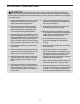
PART IDENTIFICATION CHART Use the drawings below to identify the small parts needed for assembly. The number in parentheses below each drawing is the key number of the part, from the PART LIST near the end of this manual. The number following the key number is the quantity needed for assembly. Note: If a part is not in the hardware kit, check to see if it has been preassembled. Extra parts may be included.
ASSEMBLY • To hire an authorized service technician to assemble this product, call 1-800-445-2480. • To identify small parts, see page 6. In addition to the included tool(s), assembly requires the following tools: • Assembly requires two persons. • Place all parts in a cleared area and remove the packing materials. Do not dispose of the packing materials until you finish all assembly steps. one Phillips screwdriver • Left parts are marked “L” or “Left” and right parts are marked “R” or “Right.
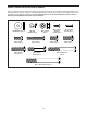
3. Orient the Front Stabilizer (2) as indicated by the sticker. 3 While a second person lifts the front of the Frame (1), attach the Front Stabilizer (2) to the Frame with two M10 x 80mm Screws (21). 21 2 1 4. Orient the Adjustment Lever (6) as shown. 4 Attach the Adjustment Lever (6) to the Brake Axle (37) with two M6 x 16mm Screws (33), two M6 Split Washers (34), and two M6 Washers (35). 37 35 34 6 33 5. Orient the Backrest Frame (8) as shown.
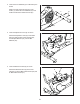
6. Orient the Seat (10) and the Seat Frame (9) as shown. 6 10 Attach the Seat (10) to the Seat Frame (9) with four M6 x 40mm Screws (27). Start all the Screws, and then tighten them. 9 27 7. Attach the Seat Frame (9) to the Seat Carriage (7) with four M8 x 40mm Screws (28). Start all the Screws, and then tighten them.
8. Orient the Backrest (11) as shown. 8 Attach the Backrest (11) to the Backrest Frame (8) with two M6 x 40mm Screws (27). 11 27 9. Remove the Accessory Tray (5) from the Left and Right Front Shields (57, 58). Set the Accessory Tray aside. Tip: It may be necessary to use a standard screwdriver to release the tabs on the Accessory Tray. 8 9 A Have a second person hold the Upright (4) near the Frame (1). 4 5 Locate the wire tie (A) inside the Upright (4).
10. Tip: Avoid pinching the Main Wire (77). Hold the Upright (4) against the Frame (1). Attach the Upright with four M8 x 15mm Screws (24). Start all the Screws, and then tighten them. 10 77 Next, orient the Accessory Tray (5) and the Console Cover (16) as shown. Avoid pinching the Main Wire (77) Tip: Avoid pinching the Main Wire (77). Slide the Accessory Tray (5) and the Console Cover (16) onto the Upright (4). Then, press the Accessory Tray onto the Left and Right Front Shields (57, 58).
. While a second person holds the Console (15) near the Handlebar (14), connect the wires on the Console to the Main Wire (77) and the Pulse Wire (50). 12 15 77 Then, insert the excess wire into the Handlebar (14). 50 14 49 49 Tip: Avoid pinching the wires. Attach the Console (15) to the Handlebar (14) with four M4 x 16mm Screws (49); start all the Screws, and then tighten them.` Avoid pinching the wires 13. Slide the Console Cover (16) upward against the Handlebar (14).
14. Attach the Tablet Holder (17) to the Console (15) with four M4 x 12mm Machine Screws (18); start all the Screws, and then tighten them. 14 17 15 18 15. Identify the Right Pedal (13). 15 Using an adjustable wrench, firmly tighten the Right Pedal (13) clockwise into the Right Crank Arm (71). Firmly tighten the Left Pedal (not shown) counterclockwise into the Left Crank Arm (not shown). IMPORTANT: You must turn the Left Pedal counterclockwise to attach it.
16. Plug the Power Adapter (80) into the receptacle on the frame of the exercise bike. 16 Note: To plug the Power Adapter (80) into an outlet, see HOW TO PLUG IN THE POWER ADAPTER on page 15. 80 17. After the exercise bike is assembled, inspect it to make sure that it is assembled correctly and that it functions properly. Make sure that all parts are properly tightened before you use the exercise bike. Extra parts may be included. Place a mat beneath the exercise bike to protect the floor.
HOW TO USE THE EXERCISE BIKE HOW TO PLUG IN THE POWER ADAPTER HOW TO ADJUST THE PEDAL STRAPS IMPORTANT: If the exercise bike has been exposed to cold temperatures, allow it to warm to room temperature before you plug in the power adapter. If you do not do this, you may damage the console displays or other electronic components. To adjust the pedal straps, first pull the ends of the straps off the tabs on the pedals.
CONSOLE DIAGRAM You can also create custom manual workouts with alternating high- and low-intensity intervals. As you exercise, the console will provide continuous exercise feedback. You can even measure your heart rate using the handgrip heart rate monitor or a compatible heart rate monitor. See page 22 for information about purchasing an optional chest heart rate monitor. You can also connect your smart device to the console and use an iFit® app to record and track your workout information.
HOW TO USE THE MANUAL MODE Note: After you press a button, it will take a moment for the pedals to reach the selected resistance level. 1. Turn on the console. 5. Do interval training, if desired. Begin pedaling or press any button on the console to turn on the console. As you exercise, you can alternate between intervals of low-intensity (recovery) exercise and intervals of high-intensity (work) exercise, if desired.
To set a power output target, press the Watts/ Kg increase and decrease buttons until the desired power output target appears in the display. 7. Follow your progress with the display. The display can show the following workout information: Note: After you set a power output target, the resistance level will automatically adjust to a preset level. You can manually override the preset level at any time. Calories (CALS)—The approximate number of calories you have burned.
Change the volume level of the console by pressing the Vol increase and decrease buttons. When your pulse is detected, your heart rate will be shown in the display. For the most accurate heart rate reading, hold the contacts for at least 15 seconds. If the display does not show your heart rate, make sure that your hands are positioned as described. Be careful not to move your hands excessively or to squeeze the contacts tightly.
HOW TO USE AN ONBOARD WORKOUT At the end of each segment of the workout, a series of tones will sound. The resistance level for the next segment will appear in the display for a few seconds to alert you. The resistance of the pedals will then change. 1. Turn on the console. Begin pedaling or press any button on the console to turn on the console. he power ring will show a flashing indicator that T represents the power output target for the segment.
5. Follow your progress with the display. HOW TO USE THE SOUND SYSTEM See step 7 on page 18. To play music or audio books through the console sound system while you exercise, plug a 3.5 mm male to 3.5 mm male audio cable (not included) into the jack on the console and into a jack on your personal audio player; make sure that the audio cable is fully plugged in. Note: To purchase an audio cable, see your local electronics store. 6. Measure your heart rate if desired. See step 8 on page 19. 7.
THE OPTIONAL CHEST HEART RATE MONITOR smart device. Make sure that the BLUETOOTH option is enabled on your smart device. Whether your goal is to burn fat or to strengthen your cardiovascular system, the key to achieving the best results is to maintain the proper heart rate during your workouts. The optional chest heart rate monitor will enable you to continuously monitor your heart rate while you exercise, helping you to reach your personal fitness goals.
HOW TO CONNECT YOUR HEART RATE MONITOR TO THE CONSOLE THE SETTINGS MODE The console features a settings mode that allows you to select a unit of measurement for the console and to view console usage information. The console is compatible with all BLUETOOTH Smart heart rate monitors. To connect your BLUETOOTH Smart heart rate monitor to the console, press the Bluetooth Smart button on the console. When a connection is established, the LED on the console will flash red twice.
FCC INFORMATION This equipment has been tested and found to comply with the limits for a Class B digital device, pursuant to part 15 of the FCC Rules. These limits are designed to provide reasonable protection against harmful interference in a residential installation. This equipment generates, uses, and can radiate radio frequency energy and, if not installed and used in accordance with the instructions, may cause harmful interference to radio communications.
MAINTENANCE AND TROUBLESHOOTING MAINTENANCE Next, locate the Reed Switch (78). Loosen, but do not remove, the M4 x 12mm Washer Head Screw (65). Regular maintenance is important for optimal performance and to reduce wear. Inspect and properly tighten all parts each time the exercise bike is used. Replace any worn parts immediately. 75 To clean the exercise bike, use a damp cloth and a small amount of mild soap.
EXERCISE GUIDELINES Burning Fat—To burn fat effectively, you must exercise at a low intensity level for a sustained period of time. During the first few minutes of exercise, your body uses carbohydrate calories for energy. Only after the first few minutes of exercise does your body begin to use stored fat calories for energy. If your goal is to burn fat, adjust the intensity of your exercise until your heart rate is near the lowest number in your training zone.
SUGGESTED STRETCHES The correct form for several basic stretches is shown at the right. Move slowly as you stretch; never bounce. 1. Toe Touch Stretch Stand with your knees bent slightly and slowly bend forward from your hips. Allow your back and shoulders to relax as you reach down toward your toes as far as possible. Hold for 15 counts, then relax. Repeat 3 times. Stretches: Hamstrings, back of knees and back. 1 2. Hamstring Stretch Sit with one leg extended.
NOTES 28
PART LIST Key No. Qty. 1 2 3 4 5 6 7 8 9 10 11 12 13 14 15 16 17 18 19 20 21 22 23 24 25 26 27 28 29 30 31 32 33 34 35 36 37 38 39 40 41 42 1 1 1 1 1 1 1 1 1 1 1 1 1 1 1 1 1 4 2 2 4 2 2 4 14 2 6 8 2 2 2 2 12 14 14 1 1 2 1 1 1 7 Model No. PFEX53915.1 R0716A Description Key No. Qty.
27 32 8 11 32 9 38 33 39 33 38 45 41 27 28 44 35 34 35 34 29 36 43 25 34 35 34 33 46 37 35 34 33 35 7 42 31 10 6 49 48 28 28 15 47 40 49 48 29 28 25 54 17 30 18 50 51 25 14 24 49 4 26 16 49 EXPLODED DRAWING A Model No. PFEX53915.
70 22 69 49 12 68 23 59 31 49 21 49 49 57 55 3 23 49 25 22 79 1 79 49 62 56 25 78 73 64 60 65 81 72 25 63 79 53 49 61 49 79 79 67 49 71 77 72 25 74 67 42 25 73 52 66 49 65 19 69 56 42 68 58 13 76 75 76 2 5 42 56 49 21 19 80 49 79 20 55 EXPLODED DRAWING B Model No. PFEX53915.
ORDERING REPLACEMENT PARTS To order replacement parts, please see the front cover of this manual.