proform.com Model No. PFRW58118.0 Serial No. Write the serial number in the space above for reference. Serial Number Decal ACTIVATE YOUR WARRANTY To register your product and activate your warranty today, go to my.proform.com. CUSTOMER CARE For service at any time, go to proformservice.com. Or call 1-888-533-1333 Mon.–Fri. 6 a.m.–6 p.m. MT Sat. 8 a.m.–12 p.m. MT Please do not contact the store. CAUTION Read all precautions and instructions in this manual before using this equipment.
TABLE OF CONTENTS WARNING DECAL PLACEMENT . . . . . . . . . . . . . . . . . . . . . . . . . . . . . . . . . . . . . . . . . . . . . . . . . . . . . . . . . . . . . . .2 IMPORTANT PRECAUTIONS. . . . . . . . . . . . . . . . . . . . . . . . . . . . . . . . . . . . . . . . . . . . . . . . . . . . . . . . . . . . . . . . . . 3 BEFORE YOU BEGIN. . . . . . . . . . . . . . . . . . . . . . . . . . . . . . . . . . . . . . . . . . . . . . . . . . . . . . . . . . . . . . . . . . . . . . . .5 PART IDENTIFICATION CHART.
IMPORTANT PRECAUTIONS WARNING: To reduce the risk of serious injury, read all important precautions and instructions in this manual and all warnings on the rower before using the rower. ICON assumes no responsibility for personal injury or property damage sustained by or through the use of this product. 1. It is the responsibility of the owner to ensure that all users of the rower are adequately informed of all precautions. sure that there is at least 2 ft. (0.6 m) of clearance around the rower. 8.
UTS STANDARD SERVICE PLANS all 4
BEFORE YOU BEGIN Thank you for selecting the new PROFORM® 750 R rower. Rowing is an effective exercise for increasing cardiovascular fitness, building endurance, and toning the body. The 750 R rower is designed to let you enjoy this effective exercise in the convenience and privacy of your home. this manual, please see the front cover of this manual. To help us assist you, note the product model number and serial number before contacting us.
PART IDENTIFICATION CHART Use the drawings below to identify the small parts needed for assembly. The number in parentheses below each drawing is the key number of the part, from the PART LIST near the end of this manual. The number following the key number is the quantity needed for assembly. Note: If a part is not in the hardware kit, check to see if it has been preassembled. Extra parts may be included.
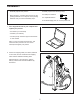
ASSEMBLY • Assembly requires two persons. • Assembly requires the following tool(s): one Phillips screwdriver • Place all parts in a cleared area and remove the packing materials. Do not dispose of the packing materials until you finish all assembly steps. one adjustable wrench To avoid damaging parts, do not use power tools. 1. Go to my.proform.com on your computer and register your product.
3. Have a second person hold the Rail (2) during this step. 3 Attach the Stabilizer (3) to the Frame (1) with two M10 x 14mm Screws (61). Then, hold the Rail Handle (34), pull the Rail (2) outward, and rest the Rail on the floor (see the drawing in step 4). 1 2 3 34 61 4. Orient the Seat (23) as shown, and slide the Seat Carriage (5) onto the Rail (2).
5. Slide the Seat (23) to the front of the Rail (2). 5 23 Next, attach the Rear Stop (87) to the Rail (2) with two M4 x 8mm Screws (104). 104 Then, attach the Rail Cap (38) to the Rail (2) with two M4 x 19mm Screws (69). 2 87 69 38 69 6. While a second person holds the Console (75) near the Upright (77), plug the Upright Wire (84) into the receptacles on the Console. 6 The connector on the Upright Wire (84) should slide easily into the receptacle and snap into place.
8. Loosen and remove the Knob (78) from the Upright (77). 8 Next, identify the Right and Left Upright Covers (80, 81), and orient them as shown. 81 68 Press the Right and Left Upright Covers (80, 81) together around the Upright (77), and attach them to the Upright with two M4 x 16mm Screws (68). 77 80 78 Then, insert the Knob (78) into the Right Upright Cover (80) and tighten it into the Upright (77). 68 9. Make sure that all parts are properly tightened. Extra parts may be included.
HOW TO USE THE ROWER HOW TO PLUG IN THE POWER ADAPTER HOW TO ADJUST THE CONSOLE VIEWING ANGLE IMPORTANT: If the rower has been exposed to cold temperatures, allow it to warm to room temperature before you plug in the Power Adapter (A). If you do not do this, you may damage the console displays or other electronic components.
HOW TO FOLD AND STORE THE ROWER Then, pull the Rail Handle (K) inward until the Folding Clamp (O) engages the bar on the Stabilizer (P). The rower can be stored in a folded position to conserve space. Store the rower in a location where children cannot tip it. Unplug the power adapter when storing the rower for extended periods of time. J To store the rower, first slide the Seat (H) to the rear of the Rail (I).
HOW TO MOVE THE ROWER IN THE UNFOLDED POSITION HOW TO ROW ON THE ROWER Sit on the seat, place your feet in the footrests, and adjust the straps to fit your feet. Then, hold the row bar with an overhand grip. Stand behind the rower and lift I the Rail (I) until the rower will roll on the wheels. Then, carefully move the rower to the desired location, and lower the Rail to the floor. Do not hold or pull on the console when moving the rower. Correct rowing form consists of three phases: 1.
CONSOLE DIAGRAM FEATURES OF THE CONSOLE The console also offers a selection of onboard workouts. Each onboard workout automatically changes the resistance of the row bar as it guides you through an effective workout. IMPORTANT: To activate your console and begin using its exclusive features, see assembly step 10 on page 10. You can even connect your personal audio player to the console sound system and listen to your favorite music or audio books while you exercise.
HOW TO USE THE MANUAL MODE approximate number of calories you have burned. When calorie workouts are selected, the approximate number of calories that remain to be burned in the workout. 1. Begin rowing or press any button on the console to turn on the console. When you turn on the console, the display will turn on. The console will then be ready for use. Calories per Hour (CALS/HR)—The approximate number of calories you are burning per hour. 2. Select the manual mode.
can mode—The console also has a scan mode S that will display workout information in a repeating cycle. To turn on the scan mode, press the Scan button (B); the scan indicator (D) and the word SCAN will turn on in the display. To pause the console, simply stop rowing or press the End button. When the console is paused, the time will flash in the display. To continue your workout, simply resume rowing. To end the workout, press the End button repeatedly. 5.
HOW TO USE AN ONBOARD WORKOUT setting by pressing the Quick Resistance buttons. IMPORTANT: When the current segment of the workout ends, the row bar will automatically adjust to the resistance level programmed for the next segment. 1. Begin rowing or press any button on the console to turn on the console. When you turn on the console, the display will turn on. The console will then be ready for use. The workout will continue in this way until the last segment ends.
HOW TO USE THE SOUND SYSTEM THE OPTIONAL CHEST HEART RATE MONITOR To play music or audio books through the console sound system while you exercise, plug a 3.5 mm male to 3.5 mm male audio cable (not included) into the jack on the console and into a jack on your personal audio player; make sure that the audio cable is fully plugged in. Note: To purchase an audio cable, see your local electronics store.
HOW TO CONNECT YOUR TABLET TO THE CONSOLE 4. Record and track your workout information. Follow the instructions in the iFit–Smart Cardio Equipment app to record and track your workout information. The console supports Bluetooth connections to tablets via the iFit–Smart Cardio Equipment app and to compatible heart rate monitors. Note: Other Bluetooth connections are not supported. 5. Disconnect your tablet from the console if desired. 1.
HOW TO CHANGE CONSOLE SETTINGS otal Distance—The letters KM will appear in the T display. The display will show the total distance in kilometers that the rower has been rowed. 1. Select the settings mode. To select the settings mode, press the Settings button. The first settings screen will appear in the display. Note: If you are using the manual mode or an onboard workout, press the End button repeatedly to end your workout before you press the Settings button.
FCC INFORMATION This equipment has been tested and found to comply with the limits for a Class B digital device, pursuant to Part 15 of the FCC Rules. These limits are designed to provide reasonable protection against harmful interference in a residential installation. This equipment generates, uses, and can radiate radio frequency energy and, if not installed and used in accordance with the instructions, may cause harmful interference to radio communications.
MAINTENANCE AND TROUBLESHOOTING MAINTENANCE HOW TO ADJUST THE REED SWITCH Regular maintenance is important for optimal performance and to reduce wear. Inspect and properly tighten all parts each time the rower is used. Replace any worn parts immediately. If the console does not display correct feedback, the reed switch should be adjusted. See EXPLODED DRAWING B on page 27. Locate the Right and Left Shields (7, 8).
EXERCISE GUIDELINES Aerobic Exercise—If your goal is to strengthen your cardiovascular system, you must perform aerobic exercise, which is activity that requires large amounts of oxygen for prolonged periods of time. For aerobic exercise, adjust the intensity of your exercise until your heart rate is near the highest number in your training zone. WARNING: Before beginning this or any exercise program, consult your physician.
PART LIST Key No. Qty. 1 2 3 4 5 6 7 8 9 10 11 12 13 14 15 16 17 18 19 20 21 22 23 24 25 26 27 28 29 30 31 32 33 34 35 36 37 38 39 40 41 42 43 44 45 46 47 48 1 1 1 1 1 2 1 1 2 1 1 1 1 1 1 2 1 1 1 1 1 1 1 2 4 2 2 2 1 1 2 2 1 1 1 2 2 1 2 2 2 4 2 5 1 2 1 1 Model No. PFRW58118.0 R1218A Description Key No. Qty.
Key No. Qty. 97 98 99 100 101 102 103 104 1 1 20 1 2 1 1 2 Description Key No. Qty. M6 x 13mm Washer M6 Washer M4 x 12mm Blunt Screw Resistance Motor M5 Nut Resistance Disc M3 x 8mm Screw M4 x 8mm Screw 105 106 107 108 109 * * 8 1 6 1 1 – – Description M4 x 12mm Screw M10 Locknut M4 x 10mm Screw Power Adapter Main Wire User’s Manual Assembly Tool Note: Specifications are subject to change without notice. For information about ordering replacement parts, see the back cover of this manual.
18 66 17 4 26 26 19 55 53 57 69 71 58 44 65 54 59 52 25 65 27 71 21 51 28 44 56 88 25 85 16 58 59 22 30 93 20 63 105 96 62 70 69 93 106 45 46 98 100 101 61 60 56 3 57 69 41 86 42 56 57 62 63 1 73 50 56 57 56 44 67 54 57 48 102 103 67 55 89 101 90 75 24 81 42 43 86 24 13 74 69 47 49 29 69 68 25 82 97 84 71 57 77 14 88 91 86 79 15 76 25 109 27 80 64 71 83 82 66 68 105 108 26 78 EXPLODED DRAWING A Model
94 63 38 39 62 94 65 40 23 37 5 56 65 57 63 57 62 55 67 56 69 72 67 69 6 36 68 107 69 104 8 35 87 2 99 68 92 99 68 31 107 95 99 99 99 99 33 32 32 31 99 99 99 99 99 107 34 99 99 99 9 99 99 7 99 10 99 11 9 69 99 99 69 68 12 68 68 6 68 68 68 EXPLODED DRAWING B Model No. PFRW58118.
ORDERING REPLACEMENT PARTS To order replacement parts, please see the front cover of this manual.