Model No. PFSY5015.1 Serial No. Write the serial number in the space above for future reference. USER’S MANUAL Serial Number Decal (Under Seat) QUESTIONS? As a manufacturer, we are committed to providing complete customer satisfaction. If you have questions, or if a part is damaged or missing, PLEASE CONTACT OUR CUSTOMER SERVICE DEPARTMENT DIRECTLY. CALL TOLL-FREE: 1-888-533-1333 Mon.–Fri., 6 a.m.–6 p.m. MST ON THE WEB: www.proformservice.
TABLE OF CONTENTS WARNING DECAL PLACEMENT . . . . . . . . . . . . . . . . . . . . . . . . . . . . . . . . . . . . . . . . . . . . . . . . . . . . . . . . . . . . . 2 IMPORTANT PRECAUTIONS . . . . . . . . . . . . . . . . . . . . . . . . . . . . . . . . . . . . . . . . . . . . . . . . . . . . . . . . . . . . . . . . 3 BEFORE YOU BEGIN . . . . . . . . . . . . . . . . . . . . . . . . . . . . . . . . . . . . . . . . . . . . . . . . . . . . . . . . . . . . . . . . . . . . . . 4 ASSEMBLY . . . . . . . . . . . . .
IMPORTANT PRECAUTIONS WARNING: To reduce the risk of serious injury, read the following important precautions before using the weight system. 1. Read all instructions in this manual and all warnings on the weight system before using the weight system. Use the weight system only as described in this manual. that the cables are on the pulleys. Replace all cables at least every two years. 10. The weight system is designed to support a maximum user weight of 300 pounds. 2.
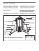
BEFORE YOU BEGIN al. To help us assist you, please note the product model number and serial number before calling. The model number is PFSY5015.1. The serial number can be found on a decal attached to the weight system (see the front cover of this manual). Thank you for selecting the versatile PROFORM® FUSION 6.0 LX weight system. The weight system offers a selection of weight stations designed to develop every major muscle group of the body.
ASSEMBLY parts of the weight system in a cleared area and remove the packing materials. Do not dispose of the packing materials until assembly is completed. Make Assembly Easier for Yourself Everything in this manual is designed to ensure that the weight system can be assembled successfully by almost anyone. Before beginning assembly, make sure to read the information on this page. This brief introduction will save you much more time than it takes to read it.
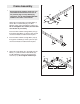
1 Frame Assembly 1. 1 Before beginning assembly, make sure you understand the information in the box on the previous page. For help identifying small parts, use the PART IDENTIFICATION CHART in the center of this manual. 109 111 112 112 Attach the Foot Plate (90) to the Right Base (1) with an M10 x 120mm Bolt (97), two M10 Washers (109), and an M10 Nylon Locknut (111). Do not overtighten the Locknut; the Foot Plate must be able to pivot easily.
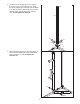
4. Orient the Center Upright (9) so the 2” Square Inner Cap (51) is in the position shown. Attach the Center Upright (9) to the Right and Left Bases (1, 2) with four M10 x 70mm Bolts (57), four M10 Washers (109), and two M10 Nylon Locknuts (111). Do not tighten the Bolts yet. 4 51 9 57 57 109 111 1 109 111 2 5. Attach the Right Upright (7) to the Right Base (1) with two M10 x 90mm Bolts (102) and two M10 Nylon Locknuts (111). Do not tighten the Locknuts yet.
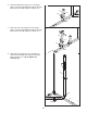
6. Attach the Right Seat Upright (11) to the Right Base (1) with the indicated M10 x 80mm Carriage Bolts (112) and two M10 Nylon Locknuts (111). 6 11 111 111 1 112 7. Attach the Curl Post Upright (10) to the Right Base (1) with the indicated M10 x 80mm Carriage Bolts (112) and two M10 Nylon Locknuts (111). 7 10 111 111 1 112 8. Attach the Left Upright (8) to the Left Base (2) with two M10 x 90mm Bolts (102) and two M10 Nylon Locknuts (111). Do not tighten the Locknuts yet.
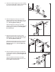
. Attach the Left Seat Upright (14) to the Left Base (2) with the indicated M10 x 80mm Carriage Bolts (112) and two M10 Nylon Locknuts (111). 9 14 111 111 2 112 10. Attach the Right Top Frame (3) to the Center Upright (9) with two M10 x 70mm Bolts (57), two M10 Washers (109), and an M10 Nylon Locknut (111). Do not tighten the Bolts yet. 10 57 3 109 111 Attach the Right Top Frame (3) to the Right Upright (7) with two M10 x 90mm Bolts (102) and two M10 Nylon Locknuts (111).
13. Orient a Weight Guide (30) with the indicated hole closer to the bottom. Attach the Weight Guide to the Center Base (5) with an M10 x 65mm Bolt (110), two M10 Washers (109), a 1/2" Spacer (68), and an M10 Nylon Locknut (111). Slide a Weight Bumper (66) onto the Weight Guide. 13 30 30 Attach the other three Weight Guides (30) to the Center Base (5) in the same manner. Tighten the M10 x 70mm Bolts (57) used in step 3. Hole 111 66 109 68 5 110 14.
15. Attach the Center Top Frame (6) to the Right and Left Top Frames (3, 4) with four M10 x 70mm Bolts (57), four M10 Washers (109), and two M10 Nylon Locknuts (111). Do not tighten the Bolts yet. 15 111 109 111 6 68 Attach a Weight Guide (30) inside the Center Top Frame (6) with an M10 x 65mm Bolt (110), two M10 Washers (109), a 1/2" Spacer (68), and an M10 Nylon Locknut (111). 109 110 109 57 109 3 Attach the other three Weight Guides (30) to the Center Top Frame (6) in the same manner.
18. Apply grease to the 1 3/4" Bushing (64). Attach the Military Press Frame (20) and the 1 3/4" Bushing inside the Left Upright (8) with an M10 x 63mm Bolt (104) and an M10 Nylon Locknut (111). 18 104 64 111 Grease 20 Hole 8 19. Apply grease to an M10 x 45mm Bolt (95). Attach the Military Press Arm (21) to the Military Press Frame (20) with the Bolt and an M10 Nylon Locknut (111). Do not overtighten the Locknut; the Military Press Arm must be able to pivot easily. 19 20 111 21 Grease 95 20.
22. Apply grease to an M10 x 70mm Bolt (57). Attach a Press Arm Handle (27) to the Left Press Arm (25) with the Bolt and an M10 Nylon Locknut (111). Do not overtighten the Locknut; the Press Arm Handle must be able to pivot easily. 22 111 57 27 Grease Repeat this step with the other Press Arm Handle (27) and the Right Press Arm (26). 25 27 26 23. Apply grease to a 2 3/4" Bushing (65). Orient the Leg Press (12) with the welded spacer on the indicated side.
26. During steps 26–53, see the PART IDENTIFICATION CHART to identify the different types of pulleys. 26 111 45 43 Wrap the Butterfly Cable (73) around a Pulley (43). Attach the Pulley, a Cable Trap (48), an M10 Washer (109), and two Finger Guards (45) to the Left Butterfly Arm (22) with an M10 x 50mm Bolt (106) and an M10 Nylon Locknut (111). Make sure that the Cable Trap is oriented to hold the Cable in the groove of the Pulley. 48 73 109 45 22 106 27.
30. Wrap the Butterfly Cable (73) over a Pulley (43). Attach the Pulley to the Right Top Frame (3) with an M10 x 40mm Bolt (116) and an M10 Nylon Locknut (111). 30 43 111 3 73 Repeat this step with another Pulley (43). 43 116 31. Wrap the Butterfly Cable (73) under a Pulley (43). Attach the Pulley, a Cable Trap (48), and two Half Finger Guards (46) at the second hole from the top of the pair of Pulley Plates (49) with an M10 x 50mm Bolt (106) and an M10 Nylon Locknut (111).
34. Attach the Butterfly Cable (73) and a Weight Cap (67) to the indicated Weight Tube (75) with an M10 x 50mm Bolt (106) and an M10 Nylon Locknut (111). 34 73 111 67 106 75 35. Locate the Low Cable (70). Route the Cable through the Leg Lever (15) and the Curl Post Upright (10). 35 Attach a Pulley (43) to the Leg Lever (15), over the Low Cable (70), with an M10 x 45mm Bolt (95) and an M10 Nylon Locknut (111). 15 10 111 43 70 95 36.
38. Wrap the Low Cable (70) over a Pulley (43). Attach the Pulley, a Cable Trap (48), and two Half Finger Guards (46) at the bottom hole of the pair of Pulley Plates (49) with an M10 x 50mm Bolt (106) and an M10 Nylon Locknut (111). Makes sure that the Cable Trap is oriented to hold the Cable in the groove of the Pulley. 38 111 49 46 46 106 48 43 70 39. Attach the Low Cable (70) inside the Right Base (1) with an M10 x 65mm Bolt (110), two M10 Washers (109), and an M10 Nylon Locknut (111).
43. Route the High Cable (88) up through the Left Top Frame (4) and over a Small Pulley (84). Attach the Pulley inside the Top Frame with an M10 x 65mm Bolt (110), two M10 Washers (109), two 1/2" Spacers (68), and an M10 Nylon Locknut (111). 43 109 68 84 110 111 88 109 68 4 44. Route the High Cable (88) over a Small Pulley (84) and down through the Left Top Frame (4).
48. Attach the High Cable (88) and a Weight Cap (67) to the indicated Weight Tube (75) with an M10 x 50mm Bolt (106) and an M10 Nylon Locknut (111). 48 88 111 67 106 75 49. Locate the Press Cable (72). Attach the Cable to the Left Base (2) with an M8 x 25mm Shoulder Bolt (92). Make sure that the Cable end can pivot easily around the shoulder of the Bolt. 49 92 2 50. Wrap the Press Cable (72) over a Pulley (43).
53. Wrap the Press Cable (72) under a Pulley (43). Attach the Pulley, a Cable Trap (48), an M10 Washer (109), and two Half Finger Guards (46) to the Left Base (2) with an M10 x 130mm Bolt (107) and an M10 Nylon Locknut (111). Make sure that the Cable Trap is oriented to hold the Cable in the groove of the Pulley. 53 46 48 109 107 111 43 72 46 2 54. Attach the Press Cable (72) to the Small Pulley Plate (50) with an M6 Washer (114) and an M6 Nylon Locknut (103). See the inset drawing.
57. Orient the Shroud Frame (89) with the indicated slot near the top. Attach the Right and Left Shrouds (32, 86) to the Shroud Frame with twelve M4 x 13mm Self-tapping Screws (105). 57 Slot 32 86 105 105 105 105 105 105 105 105 105 105 89 58. Attach the Shroud Frame (89) to the Center Top Frame (6) and to the Center Base (not shown) with two M10 x 55mm Button Bolts (115) and two M10 Washers (109).
59. Attach the Left Shroud (86) to the Left Upright (8) with six M4 x 13mm Self-tapping Screws (105). 59 105 105 Attach the Right Shroud (32) to the Right Upright (7) in the same manner. 105 105 105 8 105 7 86 32 60. Attach a Backrest (35) and a Backrest Plate (117) to the Backrest Frame (19) with four M6 x 30mm Screws (99). 60 99 117 35 19 99 61. Tighten an Adjustment Knob (69) into the Left Upright (8).
62. Attach the Large Seat (36) and the Large Seat Plate (118) to the Left Seat Frame (18) with two M6 x 30mm Screws (99), an M6 x 90mm Screw (98), and an M6 Washer (114). 62 36 118 Attach the Small Seat (not shown) and the Small Seat Plate (not shown) to the Right Seat Frame (not shown) in the same manner. 18 99 99 63. Tighten an Adjustment Knob (69) into the Left Seat Upright (14). Insert the Left Seat Frame (18) into the Seat Upright and engage the Knob into the Seat Frame.
66. Make sure that all parts have been properly tightened. The use of the remaining parts will be explained in ADJUSTMENTS, beginning below. Before using the weight system, pull each cable a few times to make sure that the cables move smoothly over the pulleys. If one of the cables does not move smoothly, find and correct the problem. IMPORTANT: If the cables are not properly installed, they may be damaged when heavy weight is used.
ADJUSTING THE BACKREST To adjust the position of the left Backrest (35), first loosen the indicated Adjustment Knob (69) and disengage it from the Backrest Frame (19). Next, move the Backrest to the desired position. Reengage the Knob into the Backrest Frame and retighten the Knob into the Left Upright (8). Make sure the Knob is fully tightened.
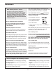
USING THE LEG LEVER LOCK When using the low pulley station, engage the Leg Lever Lock (47) onto the Leg Lever (15) tube. 47 15 TIGHTENING THE CABLES A 43 Woven cable, the type of cable used on the weight system, can stretch slightly when it is first used. If there is slack in the cables before resistance is felt, the cables should be tightened. To tighten the cables, first insert the weight pin into the middle of the weight stack.
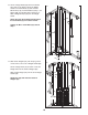
CABLE DIAGRAMS The cable diagrams below show the proper routing of the Low Cable (70), the Press Cable (72), the Butterfly Cable (73), and the High Cable (88). Use the diagrams to make sure that the cables, the cable traps, and the finger guards have been assembled correctly. If the cables have not been correctly routed, the weight system will not function properly and damage may occur. The numbers show the correct route for each cable. Make sure that the cable traps do not touch or bind the cables.
4 2 5 7 High Cable (88) Length: 13' 4 3/4" 8 1 6 3 9 6 Press Cable (72) Length: 11' 6" 4 5 1 3 28 2
WEIGHT RESISTANCE CHART The chart below shows the approximate weight resistance at each exercise station. The numbers refer to the 12.5 lb. weight plates. Weight resistance shown for the butterfly arm station is for each arm. Note: The actual resistance at each station may vary due to differences in individual weight plates as well as friction between the cables, pulleys, and weight guides. WEIGHT LOW PULLEY (lbs.) LEG LEVER (lbs.) BUTTERFLY ARM (lbs.) HIGH PULLEY (lbs.) MILITARY PRESS (lbs.
EXERCISE GUIDELINES THE FOUR BASIC TYPES OF WORKOUTS PERSONALIZING YOUR EXERCISE PROGRAM Muscle Building To increase the size and strength of your muscles, push them close to their maximum capacity. Your muscles will adapt and grow as you progressively increase the intensity of your exercise. You can adjust the intensity level of an individual exercise in two ways: • by changing the amount of weight used • by changing the number of repetitions or sets performed.
slowly as you stretch and do not bounce. Ease into each stretch gradually and go only as far as you can without strain. Stretching at the end of each workout is an effective way to increase flexibility. Rest for a short period of time after each set. The ideal resting periods are: • Rest for three minutes after each set for a muscle building workout. • Rest for one minute after each set for a toning workout. • Rest for 30 seconds after each set for a weight loss workout.
PART IDENTIFICATION CHART Refer to the drawings below to identify small parts used in assembly. The number in parentheses by each drawing is the key number of the part, from the PART LIST in the center of this manual. Note: Some small parts may have been pre-attached. If a part is not in the parts bag, check to see if it has been pre-attached.
M10 x 65mm Bolt (110) M10 x 70mm Bolt (57) "V"-pulley (44) (Not shown to scale) Pulley (43) (Not shown to scale) M10 x 75mm Bolt (96) M10 x 80mm Carriage Bolt (112) M6 x 90mm Screw (98) Small Pulley (84) (Not shown to scale) M10 x 90mm Bolt (102) M10 x 95mm Bolt (108) M10 x 100mm Bolt (85) M10 x 120mm Bolt (97) M10 x 130mm Bolt (107) M10 x 150mm Bolt (94)
PART LIST—Model No. PFSY5015.1 Key Qty. No. 1 2 3 4 5 6 7 8 9 10 11 12 13 14 15 16 17 18 19 20 21 22 23 24 25 26 27 28 29 30 31 32 33 34 35 36 37 38 39 40 41 42 43 44 45 46 47 48 49 50 51 52 53 1 1 1 1 1 1 1 1 1 1 1 1 1 1 1 1 1 1 1 1 1 1 1 1 1 1 2 1 1 4 2 1 1 24 2 1 1 1 4 3 1 8 22 1 10 16 1 10 2 1 2 1 2 R1205A Description Key Qty. No.
Key Qty. No. 107 108 109 110 111 112 113 114 115 1 1 60 16 75 6 2 3 2 Description Key Qty. No. M10 x 130mm Bolt M10 x 95mm Bolt M10 Washer M10 x 65mm Bolt M10 Nylon Locknut M10 x 80mm Carriage Bolt M10 x 35mm Screw M6 Washer M10 x 55mm Button Bolt 116 117 118 119 120 # # # # 2 2 1 1 1 1 1 1 2 Description M10 x 40mm Bolt Backrest Plate Large Seat Plate Small Seat Plate Curl Plate User’s Manual Exercise Guide Allen Wrench Grease Pack Note: “#” indicates a non-illustrated part.
EXPLODED DRAWING A—Model No. PFSY5015.
EXPLODED DRAWING B—Model No. PFSY5015.
EXPLODED DRAWING C—Model No. PFSY5015.
EXPLODED DRAWING D—Model No. PFSY5015.
ORDERING REPLACEMENT PARTS To order replacement parts, see the front cover of this manual. To help us assist you, please be prepared to give the following information: • the MODEL NUMBER of the product (PFSY5015.1) • the NAME of the product (PROFORM FUSION 6.