
Stepper Machine User Manual

11
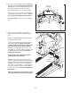
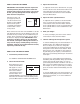
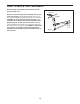
10. Apply a generous amount of the included
grease to the axles and the Cylinder Spacers
(70).
Identify an Upper Cylinder Cap (68), which has
a small hole in the center.
Hold a Shock Cylinder (69) near the bracket on
the Right Upright (72). Make sure that the
Shock Cylinder is positioned as shown with
the arrow facing the rear of the treadmill.
Attach the Shock Cylinder with a 5/16" x 5/8"
Patch Bolt (5), an Upper Cylinder Cap (68), and
an M8 Washer (10) as shown. Do not over-
tighten the Patch Bolt.
Attach the upper end of the other Shock
Cylinder (69) in the same way.
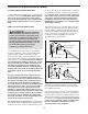
With the help of a second person, raise the
Frame (45) until the incline assembly is aligned
with the lower ends of the Shock Cylinders (69).
Attach the lower end of each Shock Cylinder
with a 3/8" x 2" Patch Bolt (3), a Lower Cylinder
Cap (90), a 3/8" Washer (11), and a Cylinder
Spacer (70) as shown. Do not overtighten the
Patch Bolts.
Make sure that both Shock Cylinders (69) are
set at the same firmness level (see page 18).
3
90
11
70
3
5
5
90
68
69
69
64
72
68
10
10
45
Incline
Assembly
70
11
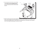
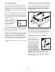
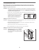
9. Set the console assembly on the Left and Right
Handrails (87, 88). Be careful not to pinch any
wires. Insert the excess Upright Wire (91) into
t
he Right Handrail, and insert the Console
Ground Wire (80) into the console assembly.
Attach the console assembly to the Handrails
(87, 88) with five #8 x 3/4" Screws (6). Start all
five Screws before tightening any of them.
See steps 4 and 6. Tighten the 3/8" Jam Nuts
(8).
80
6
6
6
91
88
8
7
6
6
9
Console
Assembly
Bracket
Grease
10
Arrow
Arrow