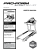
www.proform.com Model No. PFTL13214.0 Serial No. Write the serial number in the space above for reference. Serial Number Decal ACTIVATE YOUR WARRANTY To register your product and activate your warranty today, go to www.proformservice.com/ registration. CUSTOMER CARE For service at any time, go to www.proformservice.com. Or call 1-888-533-1333 Mon.–Fri. 6 a.m.–6 p.m. MT Sat. 8 a.m.–12 p.m. MT Please do not contact the store.
TABLE OF CONTENTS WARNING DECAL PLACEMENT . . . . . . . . . . . . . . . . . . . . . . . . . . . . . . . . . . . . . . . . . . . . . . . . . . . . . . . . . . . . . . .2 IMPORTANT PRECAUTIONS. . . . . . . . . . . . . . . . . . . . . . . . . . . . . . . . . . . . . . . . . . . . . . . . . . . . . . . . . . . . . . . . . . 3 BEFORE YOU BEGIN. . . . . . . . . . . . . . . . . . . . . . . . . . . . . . . . . . . . . . . . . . . . . . . . . . . . . . . . . . . . . . . . . . . . . . . .7 PART IDENTIFICATION CHART.
IMPORTANT PRECAUTIONS WARNING: To reduce the risk of burns, fire, electric shock, or injury to persons, read all important precautions and instructions in this manual and all warnings on your treadmill before using your treadmill. ICON assumes no responsibility for personal injury or property damage sustained by or through the use of this product. 1. It is the responsibility of the owner to ensure that all users of this treadmill are adequately informed of all warnings and precautions. 12.
20. Keep fingers, hair, and clothing away from the moving walking belt. 26. Never insert any object into any opening on the treadmill. 21. The treadmill is capable of high speeds. Adjust the speed in small increments to avoid sudden jumps in speed. 27. Inspect and properly tighten all parts of the treadmill regularly. 28. 22. The heart rate monitor is not a medical device. Various factors, including the user’s movement, may affect the accuracy of heart rate readings.
STANDARD SERVICE PLANS all 6
BEFORE YOU BEGIN Thank you for selecting the revolutionary PROFORM® SPORT 12.0 ST treadmill. The SPORT 12.0 ST treadmill offers an impressive selection of features designed to make your workouts at home more effective and enjoyable. And when you’re not exercising, the unique treadmill can be folded up, requiring less than half the floor space of other treadmills. reading this manual, please see the front cover of this manual.
PART IDENTIFICATION CHART Use the drawings below to identify small parts used for assembly. The number in parentheses below each drawing is the key number of the part, from the PART LIST near the end of this manual. The number following the key number is the quantity used for assembly. Note: If a part is not in the hardware kit, check to see whether it is preattached. Extra parts may be included.
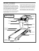
ASSEMBLY • To hire an authorized service technician to assemble the treadmill, call 1-800-445-2480 • Left parts are marked “L” or “Left” and right parts are marked “R” or “Right.” • Assembly requires two persons. • To identify small parts, see page 8. • Place all parts in a cleared area and remove the packing materials. Do not dispose of the packing materials until you finish all assembly steps.
2. Make sure that the power cord is unplugged. 2 Press a Base Cap (74) into each side of the Base (94). Next, remove the tie securing the Upright Wire (81) to the front of the Base (94). Identify the Right Upright (90). Have a second person hold the Right Upright near the Base (94). See the inset drawing. Tie the wire tie in the Right Upright (90) securely around the end of the Upright Wire (81).
4. Insert a Wheel Spacer (63) into a Front Wheel (62). Hold the Front Wheel inside the bottom of the Right Upright (90), and insert a 3/8" x 4" Screw (7) with a 3/8" Star Washer (13) into the Right Upright and the Front Wheel. 4 Repeat this step on the left side of the treadmill (not shown). 90 13 5. Place a piece of packing material (A) under the right side of the Base (94). Hold the Right Upright (90) against the Base. Make sure not to pinch the Upright Wire (81).
6. Remove and save the four indicated 5/16" x 3/4" Screws (4). 6 4 Identify the Left and Right Base Covers (82, 83). Slide the Left Base Cover onto the Left Upright (89), and slide the Right Base Cover onto the Right Upright (90). Do not press the Base Covers into place yet. 89 4 82 90 83 7. Identify the left handrail assembly (B). Attach the left handrail assembly to the Left Upright (89) with two 5/16" x 2 1/2" Screws (28) and two 5/16" Star Washers (11); do not fully tighten the Screws yet.
8. Insert the Upright Wire (81) into the bottom of the right handrail assembly (D) and out of the front as shown. 8 28 Attach the right handrail assembly (D) to the Right Upright (90) with two 5/16" x 2 1/2" Screws (28) and two 5/16" Star Washers (11); do not fully tighten the Screws yet. Make sure not to pinch the Upright Wire (81). 11 81 C D Then, remove and discard the indicated screw (C). 90 9. Set the Console Base (64) face down on a soft surface to avoid scratching the Console Base.
10. Identify the Right and Left Trays (27, 36). 10 2 2 Attach the Trays (27, 36) to the Console Base (64) with eight #8 x 1/2" Screws (1); do not overtighten the Screws. 2 41 18 Reattach the Console Frame (18) with the six #8 x 3/4" Screws (2) and the two Console Clamps (41) that you removed in step 9; do not overtighten the Screws. 41 1 27 1 2 1 1 64 36 11. IMPORTANT: To avoid damaging the Pulse Crossbar (93), do not use power tools and do not overtighten the #10 x 3/4" Screws (9).
12. Hold the console assembly (G) near the Pulse Crossbar (93). Connect the ground wire from the console assembly to the Console Ground Wire (58) on the Pulse Crossbar. 12 G Next, set the console assembly (G) on the brackets on the Handrails (86); do not pinch any wires. Make sure that the handrail wires (F) are oriented as shown. Attach the console assembly (G) with the four 5/16" x 3/4" Screws (4) that you removed in step 9 and four 5/16" Star Washers (11); do not fully tighten the Screws yet.
15. Insert the Upright Wire (81) and the other wire (F) through the two indicated looped ties on the console assembly (G). 15 G See the inset drawing. Connect the Upright Wire (81) and the other wire (F) to the console wires. The connectors should slide together easily and snap into place. If they do not, turn one connector and try again. IF YOU DO NOT CONNECT THE CONNECTORS PROPERLY, THE CONSOLE MAY BECOME DAMAGED WHEN YOU TURN ON THE POWER.
. Firmly tighten the six 3/8" x 4" Screws (7) (only one side is shown). 17 Then, press the Left Base Cover (82) and the Right Base Cover (83) onto the Base (94). 82 83 7 94 18. Note: If the treadmill is assembled on a smooth surface, it may roll forward during this step. Raise the Frame (56) to the upright position. Have a second person hold the Frame until step 20 is completed. Remove the two 5/16" x 3/4" Screws (4) from the Latch Crossbar (38).
19. Remove the 5/16" Nut (12) and the 5/16" x 1 3/4" Bolt (6) from the bracket on the Base (94). Next, orient the Storage Latch (53) as shown. Attach the lower end of the Storage Latch (53) to the bracket on the Base (94) with the 5/16" x 1 3/4" Bolt (6) and the 5/16" Nut (12). Then, raise the Storage Latch (53) to a vertical position, and remove the tie (I). 19 I 53 12 20. Remove the 5/16" Nut (12) and the 5/16" x 2 1/4" Bolt (3) from the bracket on the Latch Crossbar (38).
21. Attach the Tablet Holder (88) to the back of the console assembly (G) with four #8 x 1/2" Machine Screws (8); start all four Machine Screws, and then tighten them. Do not overtighten the Machine Screws. 21 88 G 8 8 22. Make sure that all parts are properly tightened before you use the treadmill. If there are sheets of plastic on the treadmill decals, remove the plastic. To protect the floor or carpet, place a mat under the treadmill.
HOW TO USE THE TREADMILL HOW TO CONNECT THE POWER CORD nominal 120-volt circuit capable of carrying 15 or more amps. To avoid overloading the circuit, do not plug other electrical devices, except for lowpower devices such as cell phone chargers, into the surge suppressor or into an outlet on the same circuit. IMPORTANT: The treadmill may not be compatible with AFCI-equipped outlets.
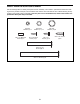
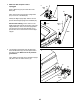
CONSOLE DIAGRAM FEATURES OF THE CONSOLE The treadmill console offers an impressive array of features designed to make your workouts more effective and enjoyable. When you use the manual mode, you can change the speed and incline of the treadmill with the touch of a button. As you exercise, the console will display instant exercise feedback. You can even measure your heart rate using the handgrip heart rate monitor or the optional chest heart rate monitor.
HOW TO TURN ON THE POWER HOW TO USE THE MANUAL MODE IMPORTANT: If the treadmill has been exposed to cold temperatures, allow it to warm to room temperature before you turn on the power. If you do not do this, you may damage the console displays or other electrical components. 1. Insert the key into the console. Plug in the power cord (see page 20). Next, locate the power switch on the treadmill frame near the power cord. Press the power switch into the reset position.
5. Follow your progress with the displays. As you exercise, the workout intensity level bar will indicate the approximate intensity level of your exercise. As you walk or run on the treadmill, the display can show the following workout information: • The elapsed time • The distance that you have walked or run • The workout intensity bar Press the Home button to return to the default menu (see HOW TO CHANGE CONSOLE SETTINGS on page 28 to set the default menu).
7. Turn on the fan if desired. HOW TO USE AN ONBOARD WORKOUT The fan features several speed settings. Press the fan buttons repeatedly to select a fan speed or to turn on or turn off the fan. 1. Insert the key into the console. See HOW TO TURN ON THE POWER on page 22. 2. Select an onboard workout. 8. When you are finished exercising, remove the key from the console. Step onto the foot rails, press the Stop button, and adjust the incline of the treadmill to zero.
4. Follow your progress with the displays. During the workout, the profiles on the speed and incline tabs Current Segment will show your progress. The flashing segment of the profile represents the current segment of the workout. The height of the flashing segment indicates the speed or incline setting for the current segment. If a different speed and/or incline setting is programmed for the next segment, the treadmill will automatically adjust to the new speed and/or incline setting.
HOW TO USE AN IFIT WORKOUT The workout will continue until you reach the goal that you set. The walking belt will then slow to a stop. Note: To use an iFit workout, you must have access to a wireless network (see pages 28 to 30). An iFit account is also required. Go to www.iFit.com to register for an iFit account. Note: The calorie goal is an estimate of the number of calories that you will burn during the workout.
9. When you are finished exercising, remove the key from the console. When you select an iFit workout, the display will show the duration of the workout, the distance you will walk or run, and the approximate number of calories you will burn. The display may also show the name of the workout. For more information about the iFit mode, go to www.iFit.com. 5. Start the workout. See step 8 on page 24.
THE OPTIONAL CHEST HEART RATE MONITOR 2. Navigate the settings mode menu. Whether your goal is to burn fat or to strengthen your cardiovascular system, the key to achieving the best results is to maintain the proper heart rate during your workouts. The optional chest heart rate monitor will enable you to continuously monitor your heart rate while you exercise, helping you to reach your personal fitness goals. To purchase a chest heart rate monitor, please see the front cover of this manual.
4. Use WiFi–Normal to set up a wireless connection. Press the Enter button to check for firmware updates using your wireless network. If an update is available, the update will begin automatically. This option will allow you to set up a wireless network connection using the console. IMPORTANT: To avoid damaging the treadmill, do not turn off the power while the firmware is being updated. The update may take several minutes. Note: You will need to know your network name (SSID).
Press the up, down, left, and right buttons to highlight the desired letter or number. Then, press the Enter button to select the letter, number, or symbol. When you have finished entering the password, press the Done button. The console will display an IP address, such as 192.168.0.1:8080. Open a web browser on your computer, smart phone, tablet, or other Wi-Fi device. Next, type in the IP address on the console into the URL bar in your browser. Example: http://192.168.0.1:8080.
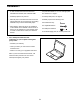
HOW TO FOLD AND MOVE THE TREADMILL HOW TO FOLD THE TREADMILL HOW TO MOVE THE TREADMILL To avoid damaging the treadmill, adjust the incline to zero before you fold the treadmill. Then, remove the key and unplug the power cord. CAUTION: You must be able to safely lift 45 lbs. (20 kg) to raise, lower, or move the treadmill. Before moving the treadmill, fold it as described at the left. CAUTION: Make sure that the storage latch is locked in the storage position. Moving the treadmill may require two people.
MAINTENANCE AND TROUBLESHOOTING MAINTENANCE SYMPTOM: The power turns off during use Regularly clean the treadmill and keep the walking belt clean and dry. First, press the power switch into the off position and unplug the power cord. Wipe exterior parts of the treadmill with a damp cloth and a small amount of mild soap. IMPORTANT: Do not spray liquids directly onto the treadmill. To avoid damage to the console, keep liquids away from the console. Then, thoroughly dry the treadmill with a soft towel. a.
SYMPTOM: The displays of the console do not function properly SYMPTOM: The walking belt slows when walked on a. Use only a surge suppressor that meets all of the specifications described on page 20. a. Remove the key from the console and UNPLUG THE POWER CORD. Next, remove the five #8 x 3/4" Screws (2). Carefully pivot off the Motor Hood (65). a 65 b. If the walking belt is overtightened, treadmill performance may decrease and the walking belt may become damaged.
SYMPTOM: The walking belt is off-center or slips when walked on SYMPTOM: The console display has lines running through it a. I f the walking belt is off-center, first remove the key and UNPLUG THE POWER CORD. If the walking belt has shifted to the left, use the hex key to turn the left idler roller screw clockwise 1/2 of a turn; if the walking belt has shifted to the right, turn the left idler roller screw counterclockwise 1/2 of a turn. Be careful not to overtighten the walking belt.
EXERCISE GUIDELINES Burning Fat—To burn fat effectively, you must exercise at a low intensity level for a sustained period of time. During the first few minutes of exercise, your body uses carbohydrate calories for energy. Only after the first few minutes of exercise does your body begin to use stored fat calories for energy. If your goal is to burn fat, adjust the intensity of your exercise until your heart rate is near the lowest number in your training zone.
SUGGESTED STRETCHES The correct form for several basic stretches is shown at the right. Move slowly as you stretch—never bounce. 1. Toe Touch Stretch Stand with your knees bent slightly and slowly bend forward from your hips. Allow your back and shoulders to relax as you reach down toward your toes as far as possible. Hold for 15 counts, then relax. Repeat 3 times. Stretches: Hamstrings, back of knees and back. 1 2. Hamstring Stretch Sit with one leg extended.
NOTES 37
PART LIST Model No. PFTL13214.0 R0115A Key No. Qty. Description Key No. Qty.
Key No. Qty. Description Key No. Qty. Description 97 98 99 100 101 102 Right Foot Pad Key/Clip Cable Tie 1/4" x 1 1/2" Screw #8 x 3/4" Washer Head Screw #8 x 3/4" Truss Head Screw Left Rear Cap Right Rear Cap 1/4" Nut Controller Clamp #8 x 1 3/4" Screw User’s Manual 1 1 3 2 6 5 103 104 105 106 107 * 1 1 1 1 2 – Note: Specifications are subject to change without notice.
15 40 24 2 103 59 30 34 23 61 44 2 37 104 35 39 2 14 26 57 43 24 15 39 35 2 14 96 2 101 24 60 4 11 97 23 45 101 92 42 24 47 46 59 30 34 30 34 102 35 39 14 2 26 19 101 59 12 14 101 21 23 92 51 100 14 35 3 39 2 14 95 49 4 11 50 55 53 101 107 52 56 38 105 10 19 48 46 23 101 20 12 6 21 100 54 59 30 34 15 102 10 107 EXPLODED DRAWING A Model No. PFTL13214.
EXPLODED DRAWING B Model No. PFTL13214.
EXPLODED DRAWING C Model No. PFTL13214.
EXPLODED DRAWING D Model No. PFTL13214.
ORDERING REPLACEMENT PARTS To order replacement parts, please see the front cover of this manual.