www.proform.com Model No. PFTL14011.2 Serial No. Write the serial number in the space above for reference. Serial Number Decal ACTIVATE YOUR WARRANTY To register your product and activate your warranty today, go to www.proformservice.com/ registration. CUSTOMER CARE For service at any time, go to www.proformservice.com. Or call 1-888-533-1333 Mon.–Fri. 6 a.m.–6 p.m. MT Sat. 8 a.m.–12 p.m. MT Please do not contact the store.
TABLE OF CONTENTS WARNING DECAL PLACEMENT . . . . . . . . . . . . . . . . . . . . . . . . . . . . . . . . . . . . . . . . . . . . . . . . . . . . . . . . . . . . . . . 2 IMPORTANT PRECAUTIONS . . . . . . . . . . . . . . . . . . . . . . . . . . . . . . . . . . . . . . . . . . . . . . . . . . . . . . . . . . . . . . . . . . 3 BEFORE YOU BEGIN. . . . . . . . . . . . . . . . . . . . . . . . . . . . . . . . . . . . . . . . . . . . . . . . . . . . . . . . . . . . . . . . . . . . . . . .
IMPORTANT PRECAUTIONS WARNING: To reduce the risk of burns, fire, electric shock, or injury to persons, read all important precautions and instructions in this manual and all warnings on your treadmill before using your treadmill. ICON assumes no responsibility for personal injury or property damage sustained by or through the use of this product. 1. Before beginning any exercise program, consult your physician.
20. Never leave the treadmill unattended while it is running. Always remove the key, press the power switch into the off position (see the drawing on page 5 for the location of the power switch), and unplug the power cord when the treadmill is not in use. 25. DANGER: Always unplug the power cord immediately after use, before cleaning the treadmill, and before performing the maintenance and adjustment procedures described in this manual.
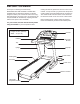
BEFORE YOU BEGIN Thank you for selecting the revolutionary PROFORM® PRO 2500 treadmill. The PRO 2500 treadmill offers an impressive selection of features designed to make your workouts at home more enjoyable and effective. And when you’re not exercising, the unique treadmill can be folded up, requiring less than half the floor space of other treadmills. reading this manual, please see the front cover of this manual.
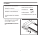
PART IDENTIFICATION CHART Use the drawings below to identify small parts used for assembly. The number in parentheses below each drawing is the key number of the part, from the PART LIST near the end of this manual. The number following the key number is the quantity used for assembly. Note: If a part is not in the hardware kit, check to see if it is preattached. Extra parts may be included.
ASSEMBLY • To hire a service technician to assemble this product in your home, call 1-800-445-2480. • To identify small parts, see page 6. • Assembly requires the following tools: • Assembly requires two persons. the included hex key • Place all parts in a cleared area and remove the packing materials. Do not dispose of the packing materials until you finish all assembly steps.
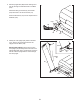
2. Pull the Upright Wire (88) and the base ground wire (A) through the indicated hole in the Base (105). 2 Attach the base ground wire (A) to the Base (105) with a #8 x 1/2" Ground Screw (10). Press the Grommet (101) into the square hole in the Base (105). Hole 101 88 A 10 3. Identify the Left Upright (90), which is marked “Left.” Have a second person hold the Left Upright near the Base (105). 105 3 88 90 See the inset drawing.
4. Hold the Left Upright (90) against the Base (105). Be careful not to pinch the wires. If necessary, position the base ground wire (A) in the hole in the side of the Left Upright. Insert two 3/8" x 2 3/4" Screws (8) and two 3/8" x 1 1/4" Screws (9) with two 3/8" Star Washers (14) into the Left Upright. 4 Partially tighten the 3/8" x 2 3/4" Screws (8) and the 3/8" x 1 1/4" Screws (9) until the heads of the Screws touch the Left Upright (90); do not fully tighten the Screws yet.
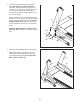
6. Remove the four 3/8" x 1" Screws (6) and four 3/8" Star Washers (14) from the Handrail Brackets (89). Then, remove the Handrail Brackets from the Left and Right Handrails (92, 93). The Screws and Star Washers will be used in step 8. 6 6 14 89 6 14 6 14 93 89 6 14 92 7. Remove the four 3/8" x 1" Flat Head Screws (15) and four 3/8" Star Washers (14) from the Left and Right Uprights (90, 99). 7 Hole 15 89 Orient the Handrail Brackets (89) so that the indicated holes are in the positions shown.
9. Remove and discard the #10 x 3/4" Screws (3) from the Right Handrail (93) and the Left Handrail (not shown). 9 93 Pulse Wire 3 Hold the pulse assembly near the Right Handrail (93). Insert the pulse wire from the pulse assembly into the hole in the side of the Right Handrail and out of the end of the Right Handrail as shown. Pulse Assembly Hole 10. Slide the pulse assembly onto the Left and Right Handrails (92, 93).
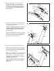
. With the help of a second person, hold the console assembly near the Uprights (90, 99). 12 Console Assembly Connect the Upright Wire (88) to the console wire. See the inset drawing. The connectors should slide together easily and snap into place. If they do not, turn one connector and try again. IF YOU DO NOT CONNECT THE CONNECTORS PROPERLY, THE CONSOLE MAY BECOME DAMAGED WHEN YOU TURN ON THE POWER. 88 Pulse Wires Next, connect the two pulse wires.
14. Attach a Tray Bracket (91) to the side of the Right Upright (99) with two #8 x 3/4" Screws (2). Make sure to use the two holes shown. Start both Screws, and then tighten them. 14 87 Attach the other Tray Bracket (not shown) to the Left Upright (not shown) in the same way. 91 Attach the Tray (87) to the Tray Brackets (91) with four #8 x 3/4" Screws (2) (only one side is shown). Start all four Screws, and then tighten them. 2 99 15.
17. Attach the upper end of the Storage Latch (65) to the Frame (64) with a 3/8" x 1 3/4" Bolt (7) and a 3/8" Nut (13). Note: It may be necessary to move the Frame back and forth to align the Storage Latch with the Base (not shown). 17 64 13 7 65 18. Lower the Frame (64) (see HOW TO LOWER THE TREADMILL FOR USE on page 29).
THE CHEST HEART RATE MONITOR HOW TO PUT ON THE HEART RATE MONITOR The heart rate monitor consists of a chest strap and a sensor. Insert the tab on one end of the chest strap into the hole in one end of the sensor as shown. Then, press the end of the sensor under the buckle on the chest strap. The tab should be flush with the front of the sensor.
OPERATION AND ADJUSTMENT HOW TO CONNECT THE POWER CORD nominal 120-volt circuit capable of carrying 15 or more amps. To avoid overloading the circuit, do not plug other electrical devices, except for lowpower devices such as cell phone chargers, into the surge suppressor or into an outlet on the same circuit. IMPORTANT: The treadmill is not compatible with GFCI-equipped outlets and may not be compatible with AFCI-equipped outlets.
CONSOLE DIAGRAM FEATURES OF THE CONSOLE As you exercise, the console will display instant exercise feedback. You can also measure your heart rate using the handgrip heart rate monitor or the chest heart rate monitor. The treadmill console offers an impressive array of features designed to make your workouts more effective and enjoyable. The console features revolutionary iFit technology that enables the treadmill to communicate with your wireless network.
HOW TO TURN ON THE POWER HOW TO USE THE TOUCH SCREEN IMPORTANT: If the treadmill has been exposed to cold temperatures, allow it to warm to room temperature before you turn on the power. If you do not do this, you may damage the console displays or other electrical components. The console features a tablet with a full-color touch screen. The following information will help you become familiar with the tablet’s advanced technology: Plug in the power cord (see page 16).
HOW TO SET UP THE CONSOLE The browser will open to the iFit.com registration page. Touch the Buy Now button to register for an iFit account. If you have an activation code, select the code activation option. Then, follow the prompts on the screen to sign up for your iFit membership. Before using the treadmill for the first time, set up the console. 1. Connect to your wireless network. The console is now ready for you to begin working out.
HOW TO USE THE MANUAL MODE Each time you press one of the buttons, the incline will gradually change until it reaches the selected incline setting. 1. Insert the key into the console. See HOW TO TURN ON THE POWER on page 18. Note: It may take a minute for the console to be ready for use. Note: The first time you adjust the incline, you must first calibrate the incline system (see step 4 on page 26). 2. Select the main menu. 5. Monitor your progress.
If desired, adjust the volume by pressing the Vol increase and decrease buttons on the console. 7. Turn on the fan if desired. The fan features multiple speed settings and an auto mode. When the auto mode is selected, the speed of the fan will automatically increase and decrease as the speed of the walking belt increases and decreases. To pause the workout, touch one of the menu buttons or press the Stop button on the console. To continue the workout, touch the Resume button or the Start button.
HOW TO USE AN ONBOARD WORKOUT the Finish button to return to the main menu. You may also be able to either save or publish your results using one of the options on the screen. 1. Insert the key into the console. See HOW TO TURN ON THE POWER on page 18. If the speed and/or incline settings are too high or too low at any time during the workout, you can override the settings by pressing the Speed or Incline buttons.
HOW TO USE A SET-A-GOAL WORKOUT The workout will function in the same way as the manual mode (see pages 20 and 21). 1. Insert the key into the console. The workout will continue until you reach the goal that you set. The walking belt will then slow to a stop, and a workout summary will appear on the screen. After you view the workout summary, touch the Finish button to return to the main menu. You may also be able to either save or publish your results using one of the options on the screen.
HOW TO USE AN IFIT WORKOUT Before some workouts will download, you must add them to your schedule on iFit.com. Note: To use an iFit workout, you must have access to a wireless network (see HOW TO USE THE WIRELESS NETWORK MODE on page 27). An iFit account is also required. For more information about the iFit workouts, please see www.iFit.com. When you select an iFit workout, the screen will show the name, duration, and distance of the workout.
HOW TO USE THE EQUIPMENT SETTINGS MODE the power cord, press the power switch into the reset position, and insert the key into the console. However, when you remove the key, the screen will show a demo presentation. 1. Select the settings main menu. Insert the key into the console (see HOW TO TURN ON THE POWER on page 18). Next, select the main menu (see step 2 on page 20). Then, touch the gears button near the lower right corner of the screen to select the settings main menu.
12. Set a safety screen timeout. The screen will show the progress of the update. When the update is complete, the treadmill will turn off and then turn back on. If it does not, press the power switch into the off position. Wait for several seconds, and then press the power switch into the reset position. Note: It may take a few minutes for the console to be ready for use.
HOW TO USE THE WIRELESS NETWORK MODE An information box will ask if you want to connect to the wireless network. Touch the Connect button to connect to the network or touch the Cancel button to return to the list of networks. If the network has a password, touch the password entry box. A keyboard will appear on the screen. To view the password as you type it, touch the Show Password checkbox. The console features a wireless network mode that allows you to set up a wireless network connection. 1.
HOW TO USE THE SOUND SYSTEM HOW TO USE THE INTERNET BROWSER To play music or audio books through the console sound system while you exercise, plug a 3.5 mm male to 3.5 mm male audio cable (not included) into the jack on the console and into a jack on your MP3 player, CD player, or other personal audio player; make sure that the audio cable is fully plugged in. Note: To purchase an audio cable, see your local electronics store.
HOW TO FOLD AND MOVE THE TREADMILL HOW TO FOLD THE TREADMILL HOW TO MOVE THE TREADMILL To avoid damaging the treadmill, adjust the incline to 0 percent before you fold the treadmill. Then, remove the key and unplug the power cord. CAUTION: You must be able to safely lift 45 lbs. (20 kg) to raise, lower, or move the treadmill. Before moving the treadmill, fold it as described at the left. CAUTION: Make sure that the latch knob is locked in the storage position. Moving the treadmill may require two people.
TROUBLESHOOTING Most treadmill problems can be solved by following the simple steps below. Find the symptom that applies, and follow the steps listed. If further assistance is needed, see the front cover of this manual. c. Remove the key from the console, and then reinsert it. d. If the treadmill still will not run, please see the front cover of this manual. SYMPTOM: The power does not turn on SYMPTOM: The console displays remain lit when you remove the key from the console a.
Lower the treadmill (see HOW TO LOWER THE TREADMILL FOR USE on page 29). Remove the three #8 x 3/4" Screws (2). Carefully pivot the Motor Hood (72) off. 72 SYMPTOM: The walking belt slows when walked on a. Use only a single-outlet surge suppressor that meets all of the specifications described on page 16. b. If the walking belt is overtightened, treadmill performance may decrease and the walking belt may become damaged. Remove the key and UNPLUG THE POWER CORD.
SYMPTOM: The walking belt is off-center or slips when walked on SYMPTOM: The iFit mode does not function correctly a. If the walking belt is off-center, first remove the key and UNPLUG THE POWER CORD. If the walking belt has shifted to the left, use the hex key to turn the left idler roller screw clockwise 1/2 of a turn; if the walking belt has shifted to the right, turn the left idler roller screw counterclockwise 1/2 of a turn. Be careful not to overtighten the walking belt.
EXERCISE GUIDELINES Burning Fat—To burn fat effectively, you must exercise at a low intensity level for a sustained period of time. During the first few minutes of exercise, your body uses carbohydrate calories for energy. Only after the first few minutes of exercise does your body begin to use stored fat calories for energy. If your goal is to burn fat, adjust the intensity of your exercise until your heart rate is near the lowest number in your training zone.
PART LIST Key No. Qty. 1 2 3 4 5 6 7 8 9 10 11 12 13 14 15 16 17 18 19 20 21 22 23 24 25 26 27 28 29 30 31 32 33 34 35 36 37 38 39 40 41 42 43 44 45 46 47 48 49 50 9 46 4 4 1 4 1 4 4 7 4 4 2 12 6 29 2 2 10 8 1 1 2 4 2 2 2 2 16 8 1 1 2 2 2 6 12 3 2 8 2 1 1 1 1 8 1 1 1 1 Model No. PFTL14011.2 R1213A Description Key No. Qty.
Key No. Qty. 101 102 103 104 105 106 107 108 109 110 2 2 1 2 1 1 1 1 0 1 Description Key No. Qty. Grommet Front Base Pad Left Wheel Cap Wheel Base Heart Rate Strap Heart Rate Sensor Console Base Not Used Left Tray 111 112 113 114 115 116 117 118 119 * 1 1 1 4 1 6 1 1 1 – Description Right Tray Console Console Frame Console Clamp Console Ground Wire Cable Tie Right Handrail Cover Left Handrail Cover Right Wheel Cap User’s Manual Note: Specifications are subject to change without notice.
17 48 16 16 95 19 19 27 39 33 37 29 19 49 16 41 71 29 45 44 50 51 69 19 70 54 29 46 17 46 52 30 37 40 46 53 16 37 40 19 27 39 33 37 16 40 37 46 40 29 16 37 16 69 41 70 29 46 30 37 40 24 47 16 54 52 30 19 16 55 2 16 40 37 57 7 29 46 16 16 28 37 30 68 13 63 56 26 16 40 30 46 64 42 37 30 58 43 16 29 40 37 61 62 16 23 59 67 65 2 29 46 55 10 24 30 60 28 25 66 13 16 56 37 31 32 5 26 10 30 23 EXPLODED
EXPLODED DRAWING B Model No. PFTL14011.
EXPLODED DRAWING C Model No. PFTL14011.
EXPLODED DRAWING D 106 Model No. PFTL14011.
ORDERING REPLACEMENT PARTS To order replacement parts, please see the front cover of this manual.