www.proform.com Model No. PFTL59013.4 Serial No. Write the serial number in the space above for reference. Serial Number Decal ACTIVATE YOUR WARRANTY To register your product and activate your warranty today, go to www.proformservice.com/ registration. CUSTOMER CARE For service at any time, go to www.proformservice.com. Or call 1-888-533-1333 Mon.–Fri. 6 a.m.–6 p.m. MT Sat. 8 a.m.–12 p.m. MT Please do not contact the store.
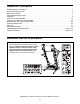
TABLE OF CONTENTS WARNING DECAL PLACEMENT . . . . . . . . . . . . . . . . . . . . . . . . . . . . . . . . . . . . . . . . . . . . . . . . . . . . . . . . . . . . . . .2 IMPORTANT PRECAUTIONS. . . . . . . . . . . . . . . . . . . . . . . . . . . . . . . . . . . . . . . . . . . . . . . . . . . . . . . . . . . . . . . . . . 3 BEFORE YOU BEGIN. . . . . . . . . . . . . . . . . . . . . . . . . . . . . . . . . . . . . . . . . . . . . . . . . . . . . . . . . . . . . . . . . . . . . . . .6 PART IDENTIFICATION CHART.
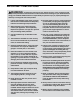
IMPORTANT PRECAUTIONS WARNING: To reduce the risk of burns, fire, electric shock, or injury to persons, read all important precautions and instructions in this manual and all warnings on your treadmill before using your treadmill. ICON assumes no responsibility for personal injury or property damage sustained by or through the use of this product. 1. It is the responsibility of the owner to ensure that all users of this treadmill are adequately informed of all warnings and precautions. 12.
25. When folding or moving the treadmill, make sure that the storage latch is holding the frame securely in the storage position. 20. Keep fingers, hair, and clothing away from the moving walking belt. 21. The treadmill is capable of high speeds. Adjust the speed in small increments to avoid sudden jumps in speed. 26. Do not change the incline of the treadmill by placing objects under the treadmill. 27. Never insert any object into any opening on the treadmill. 22.
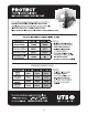
STANDARD SERVICE PLANS all 5
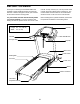
BEFORE YOU BEGIN Thank you for selecting the new PROFORM® ZT6 treadmill. The ZT6 treadmill provides an impressive selection of features designed to make your workouts at home more effective and enjoyable. manual. To help us assist you, note the product model number and serial number before contacting us. The model number and the location of the serial number decal are shown on the front cover of this manual. For your benefit, read this manual carefully before you use the treadmill.
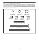
PART IDENTIFICATION CHART Use the drawings below to identify small parts used for assembly. The number in parentheses below each drawing is the key number of the part, from the PART LIST near the end of this manual. The number following the key number is the quantity used for assembly. Note: If a part is not in the hardware kit, check to see whether it is preattached. Extra parts may be included.
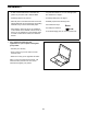
ASSEMBLY • To hire a service technician to assemble this product in your home, call 1-800-445-2480. • Left parts are marked “L” or “Left” and right parts are marked “R” or “Right.” • Assembly requires two persons. • To identify small parts, see page 7. • Place all parts in a cleared area and remove the packing materials. Do not dispose of the packing materials until you finish all assembly steps.
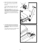
2. Make sure that the power cord is unplugged. 2 Press a Base Cap (74) into each side of the Base (85). Identify the Right Upright (90). Have a second person hold the Right Upright near the Base (85). See the inset drawing. Tie the wire tie in the Right Upright (90) securely around the end of the Upright Wire (81). Then, insert the Upright Wire into the lower end of the Right Upright as you pull the other end of the wire tie out of the Right Upright.
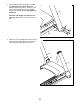
4. Hold the Right Upright (90) against the Base (85). Be careful not to pinch the wires. Partially tighten three 3/8" x 4" Screws (7) with three 3/8" Star Washers (13) into the Right Upright and the Base; do not fully tighten the Screws yet. 4 90 Attach the Left Upright (not shown) in the same way. Note: There are no wires on the left side. 13 7 Wires 85 5. Identify the Left and Right Base Covers (82, 83). Slide the Left and Right Base Covers onto the Left and Right Uprights (89, 90) as shown.
6. Set a Handrail (84) onto the Right Upright (90). Make sure that the Upright Wire (81) is not pinched. 6 28 Attach the Handrail (84) with two 5/16" x 2 1/4" Screws (28) and two 5/16" Star Washers (11); start both Screws, and then tighten them. 11 84 Attach the other Handrail (not shown) in the same way. Note: There is no wire on the left side. 81 Then, remove and discard the two indicated screws (A) in each Handrail (84) (only one side is shown). 7.
8. With the help of a second person, hold the console assembly near the Handrails (84) (only one side is shown). 8 Console Assembly See the inset drawing. Connect the Upright Wire (81) to the console wire. The connectors should slide together easily and snap into place. If they do not, turn one connector and try again. IF YOU DO NOT CONNECT THE CONNECTORS PROPERLY, THE CONSOLE MAY BECOME DAMAGED WHEN YOU TURN ON THE POWER. Then, remove the wire tie from the Upright Wire.
10. IMPORTANT: To avoid damaging the Pulse Crossbar (5), do not use power tools and do not overtighten the #10 x 3/4" Screws (9). 10 Tighten four #10 x 3/4" Screws (9) with four 1/4" Star Washers (26) into the Pulse Crossbar (5) and the Handrails (84). Start all four Screws, and then tighten them. 9 26 See step 9. Tighten the four 1/4" x 1/2" Screws (2). 84 9 26 84 11. Identify the Left and Right Handrail Inserts (79, 31).
12. Identify the Left and Right Handrail Covers (87, 8). Slide the Left Handrail Cover (87) up against the console assembly and tighten a #8 x 3/4" Screw (4) into the bottom of the Left Handrail Cover; do not overtighten the Screw. Attach the Right Handrail Cover (8) in the same way. 12 Console Assembly 87 4 8 4 13. Orient the Latch Assembly (62) so that the knob is on the side shown.
14. Firmly tighten all six 3/8" x 4" Screws (7). Then, slide the Left and Right Base Covers (82, 83) downward. 14 82 7 83 7 15. Make sure that all parts are properly tightened before you use the treadmill. If there are sheets of plastic on the treadmill decals, remove the plastic. To protect the floor or carpet, place a mat under the treadmill. To avoid damage to the console, keep the treadmill out of direct sunlight.
HOW TO USE THE TREADMILL HOW TO CONNECT THE POWER CORD nominal 120-volt circuit capable of carrying 15 or more amps. To avoid overloading the circuit, do not plug other electrical devices, except for lowpower devices such as cell phone chargers, into the surge suppressor or into an outlet on the same circuit. IMPORTANT: The treadmill may not be compatible with AFCI-equipped outlets.
CONSOLE DIAGRAM To turn on the power, see page 18. To use the manual mode, see page 18. To use an onboard workout, see page 20. To use the information mode, see page 21. To use the sound system, see page 21. FEATURES OF THE CONSOLE The treadmill console offers an impressive array of features designed to make your workouts more effective and enjoyable. When you use the manual mode, you can change the speed and incline of the treadmill with the touch of a button.
HOW TO TURN ON THE POWER HOW TO USE THE MANUAL MODE IMPORTANT: If the treadmill has been exposed to cold temperatures, allow it to warm to room temperature before you turn on the power. If you do not do this, you may damage the console displays or other electrical components. 1. Insert the key into the console. Plug in the power cord (see page 16). Next, locate the power switch on the treadmill frame near the power cord. Press the power switch into the reset position.
5. Follow your progress with the displays. 6. Measure your heart rate if desired. When you select the manual mode, a track representing 1/4 mile (400 m) will appear in the matrix. As you walk or run on the treadmill, the indicators around the track will appear in succession until the entire track appears. The track will then disappear and the indicators will again begin to appear in succession. Before using the handgrip heart rate monitor, remove the sheets of plastic from the metal contacts.
HOW TO USE AN ONBOARD WORKOUT 1. Insert the key into the console. See HOW TO TURN ON THE POWER on page 18. 2. Select an onboard workout. To select an onboard workout, press the Calorie button, the Intensity button, the Speed button, or the Incline button repeatedly until the desired workout appears in the display. The workout will continue in this way until the last segment of the profile flashes in the display and the last segment ends. The walking belt will then slow to a stop.
4. Follow your progress with the displays. The console features a display demo mode, designed to be used if the treadmill is displayed in a store. While the demo mode is turned on, the console will function normally when you plug in the power cord, press the power switch into the reset position, and insert the key into the console. However, when you remove the key, the displays will remain lit, although the buttons will not function.
HOW TO FOLD AND MOVE THE TREADMILL HOW TO FOLD THE TREADMILL HOW TO MOVE THE TREADMILL To avoid damaging the treadmill, adjust the incline to zero before you fold the treadmill. Then, remove the key and unplug the power cord. CAUTION: You must be able to safely lift 45 lbs. (20 kg) to raise, lower, or move the treadmill. Before moving the treadmill, fold it as described at the left. CAUTION: Make sure that the latch knob is locked in the storage position. Moving the treadmill may require two people. 1.
MAINTENANCE AND TROUBLESHOOTING MAINTENANCE SYMPTOM: The power turns off during use Regularly clean the treadmill and keep the walking belt clean and dry. First, press the power switch into the off position and unplug the power cord. Wipe exterior parts of the treadmill with a damp cloth and a small amount of mild soap. IMPORTANT: Do not spray liquids directly onto the treadmill. To avoid damage to the console, keep liquids away from the console. Then, thoroughly dry the treadmill with a soft towel. a.
SYMPTOM: The walking belt slows when walked on ext, locate the Reed Switch (52) and the Magnet N (50) on the left side of the Pulley (49). Turn the Pulley until the Magnet is aligned with the Reed Switch. Make sure that the gap between the Magnet and the Reed Switch is about 1/8 in. (3 mm). If necessary, loosen the #8 x 3/4" Truss Head Screw (14), move the Reed Switch slightly, and then retighten the Screw.
SYMPTOM: The walking belt is off-center or slips when walked on b. I f the walking belt slips when walked on, first remove the key and UNPLUG THE POWER CORD. Using the hex key, turn both idler roller screws clockwise, 1/4 of a turn. When the walking belt is correctly tightened, you should be able to lift each edge of the walking belt 2 to 3 in. (5 to 7 cm) off the walking platform. Be careful to keep the walking belt centered.
EXERCISE GUIDELINES Burning Fat—To burn fat effectively, you must exercise at a low intensity level for a sustained period of time. During the first few minutes of exercise, your body uses carbohydrate calories for energy. Only after the first few minutes of exercise does your body begin to use stored fat calories for energy. If your goal is to burn fat, adjust the intensity of your exercise until your heart rate is near the lowest number in your training zone.
PART LIST Model No. PFTL59013.4 R1114A Key No. Qty. Description Key No. Qty.
15 14 59 30 34 23 66 39 14 28 14 40 43 61 37 14 57 44 15 35 66 39 14 1 37 41 14 40 23 42 14 45 35 46 47 59 30 34 37 19 30 56 35 37 60 34 59 21 50 51 23 37 66 14 35 53 10 39 14 49 52 55 66 39 14 48 20 19 54 37 59 30 34 53 46 23 10 21 10 73 10 24 EXPLODED DRAWING A Model No. PFTL59013.
EXPLODED DRAWING B Model No. PFTL59013.
EXPLODED DRAWING C Model No. PFTL59013.
EXPLODED DRAWING D Model No. PFTL59013.
ORDERING REPLACEMENT PARTS To order replacement parts, please see the front cover of this manual.