proform.com Model No. PFTL59721.0 Serial No. Write the serial number in the space above for reference. Serial Number Decal ACTIVATE YOUR WARRANTY To register your product and activate your warranty today, go to my.proform.com. CUSTOMER CARE For service at any time, go to support.proform.com. Or call 1-888-533-1333 Mon.–Fri. 6 a.m.–6 p.m. MT Sat. 8 a.m.–12 p.m. MT Please do not contact the store. CAUTION Read all precautions and instructions in this manual before using this equipment.
TABLE OF CONTENTS WARNING DECAL PLACEMENT . . . . . . . . . . . . . . . . . . . . . . . . . . . . . . . . . . . . . . . . . . . . . . . . . . . . . . . . . . . . . . .2 IMPORTANT PRECAUTIONS. . . . . . . . . . . . . . . . . . . . . . . . . . . . . . . . . . . . . . . . . . . . . . . . . . . . . . . . . . . . . . . . . . 3 BEFORE YOU BEGIN. . . . . . . . . . . . . . . . . . . . . . . . . . . . . . . . . . . . . . . . . . . . . . . . . . . . . . . . . . . . . . . . . . . . . . . .6 PART IDENTIFICATION CHART.
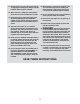
IMPORTANT PRECAUTIONS WARNING: To reduce the risk of burns, fire, electric shock, or injury to persons, read all important precautions and instructions in this manual and all warnings on your treadmill before using your treadmill. ICON assumes no responsibility for personal injury or property damage sustained by or through the use of this product. 1. It is the responsibility of the owner to ensure that all users of this treadmill are adequately informed of all warnings and precautions. 12.
19. Always stand on the foot rails when starting or stopping the walking belt. Always hold the handrails while using the treadmill. 25. When folding or moving the treadmill, make sure that the storage latch is holding the frame securely in the storage position. Do not operate the treadmill while it is folded. 20. When a person is walking on the treadmill, the noise level of the treadmill will increase. 26. Do not change the incline of the treadmill by placing objects under the treadmill. 21.
STANDARD SERVICE PLANS all 5
BEFORE YOU BEGIN Thank you for selecting the new PROFORM® TRAINER 8.0 treadmill. The TRAINER 8.0 treadmill provides an impressive selection of features designed to make your workouts at home more effective and enjoyable. reading this manual, please see the front cover of this manual. To help us assist you, note the product model number and serial number before contacting us. The model number and the location of the serial number decal are shown on the front cover of this manual.
PART IDENTIFICATION CHART Use the drawings below to identify small parts used for assembly. The number in parentheses below each drawing is the key number of the part, from the PART LIST near the end of this manual. The number following the key number is the quantity used for assembly. Note: If a part is not in the hardware kit, check to see whether it is preattached. Extra parts may be included.
ASSEMBLY • To hire a service technician to assemble this product in your home, call 1-800-445-2480. • Left parts are marked “L” or “Left” and right parts are marked “R” or “Right.” • Assembly requires two persons. • To identify small parts, see page 7. • Place all parts in a cleared area and remove the packing materials. Do not dispose of the packing materials until you finish all assembly steps.
2. Make sure that the power cord is unplugged. 2 Remove the tie securing the Upright Wire (88) to the front of the Base (97). A 88 Next, identify the Right Upright (86). Have a second person hold the Right Upright near the Base (97). 88 86 See the inset drawing. Tie the wire tie (A) in the Right Upright (86) securely around the end of the Upright Wire (88).
4. Hold the Right Upright (86) against the Base (97). Make sure not to pinch the Upright Wire (89). 4 Insert two 3/8" x 2 3/8" Screws (3) with two 3/8" Star Washers (11) into the top of the bracket on the Right Upright (86). Partially tighten the two Screws into the Base (97); do not fully tighten the Screws yet. Then, partially tighten a 3/8" x 1 1/4" Screw (1) and a 3/8" x 1 3/4" Screw (2) with 3/8" Star Washers (11) into the bottom of the Right Upright (86); do not fully tighten the Screws yet.
6. Identify the Left and Right Handrails (80, 81). Attach the Right Handrail (81) to the Right Upright (86) with two 5/16" x 2 1/4" Screws (7) and two 5/16" Star Washers (12) in the location shown; start both Screws, and then tighten them. Make sure not to pinch the Upright Wire (88), and make sure that the wire is on the indicated side of the Right Upright. 6 7 E 12 80 7 85 Attach the Left Handrail (80) to the Left Upright (85) in the same way. Note: There are no wires on the left side.
8. With the help of a second person, hold the console assembly (F) near the Right Upright (86). 8 F Next, insert the Upright Wire (88) through the indicated looped tie (G). Connect the Upright Wire (88) to the wire (H) from the console assembly (F). The connectors should slide together easily and snap into place. If they do not, turn one connector and try again. Then, remove any wire ties (A) from the Upright Wire (88). 87 88 G H 86 A 9.
10. IMPORTANT: To avoid damaging the Crossbar (87), do not use power tools and do not overtighten the #10 x 3/4" Screws (6). 10 Attach the Crossbar (87) to the Handrails (80, 81) with four #10 x 3/4" Screws (9) and four 1/4" Star Washers (10); start all four Screws, and then tighten them. 10 80 6 10 87 6 10 81 11. Identify the Right Handrail Cover (79).
12. Orient the Storage Latch (84) as shown. Attach the Storage Latch to the Left Upright (85) with two 1/4" x 4 1/2" Screws (8) and two 1/4" Star Washers (10); start both Screws, and then tighten them. 12 10 8 84 13. Firmly tighten the four 3/8" x 2 3/8" Screws (3), the two 3/8" x 1 1/4" Screws (1), and the two 3/8" x 1 3/4" Screws (2). 85 13 85 Next, set the Left Inner Base Cover (95) onto the lower end of the Left Upright (85).
14. IMPORTANT: You must activate your Console (105) to begin using its exclusive features. 14 105 First, plug in the power cord (see page 16) and turn on the power (see page 18). Then, using your smartphone or tablet, go to iFit.com/activate and follow the instructions to activate the Console (105). Note: If you do not have a smartphone or tablet, use your computer to go to iFit.com/activate for an alternate way to activate the Console (105).
HOW TO USE THE TREADMILL HOW TO CONNECT THE POWER CORD capable of carrying 15 or more amps. To avoid overloading the circuit, do not plug other electrical devices, except for low-power devices such as cell phone chargers, into the surge suppressor or into an outlet on the same circuit. IMPORTANT: If the treadmill is connected to an AFCI-equipped outlet and your circuit breaker trips repeatedly when the treadmill is used, see the front cover of this manual to purchase an arc filter.
CONSOLE DIAGRAM FEATURES OF THE CONSOLE You can even listen to your favorite workout music or audio books with the console’s sound system while you exercise. I MPORTANT: To activate your console and begin using its exclusive features, see assembly step 14 on page 15. To turn on the power, see page 18. To use the manual mode, see page 18. To use an onboard workout, see page 20. To use an iFit workout, see page 21. To connect a heart rate monitor to the console, see page 22.
HOW TO TURN ON THE POWER HOW TO USE THE MANUAL MODE IMPORTANT: If the treadmill has been exposed to cold temperatures, allow it to warm to room temperature before you turn on the power. If you do not do this, you may damage the console displays or other electrical components. 1. Insert the key into the console. Plug in the power cord (see page 16). Next, locate the power switch on the treadmill frame near the power cord. Press the power switch into the reset position (I).
5. Follow your progress with the display. To manually advance the scan cycle, press the Scan button repeatedly. The display can show the following workout information: To turn off the scan mode, press the Display button; the scan indicator and the word SCAN will turn off. Calories (CALS)—The approximate number of calories you have burned. You can also customize the scan mode to display only the desired workout information in the repeating cycle.
HOW TO USE AN ONBOARD WORKOUT The workout will continue in this way until the last segment ends. The walking belt will then slow to a stop. 1. Insert the key into the console. See HOW TO TURN ON THE POWER on page 18.
HOW TO USE AN IFIT WORKOUT 4. Select an iFit workout. The console offers access to a large and varied library of iFit workouts when you download the iFit app to your smart device and connect it to the console. In the iFit app, touch the buttons at the bottom of the screen to select either the main menu (Home button) or the workout library (Browse button). Note: The console supports Bluetooth connections to smart devices via the iFit app and to compatible heart rate monitors.
HOW TO CONNECT A HEART RATE MONITOR TO THE CONSOLE To pause the workout, simply touch the screen or press the Stop button. To continue the workout, press the play icon on the screen, or press the Start button. The console is compatible with Bluetooth Smart heart rate monitors. For information about purchasing an optional chest heart rate monitor, see page 24.
THE SETTINGS MODE Unit of Measurement—The currently selected unit of measurement will appear in the display. The console can show speed and distance in standard or metric units of measurement. To change the unit of measurement, press the Speed increase button repeatedly. To view workout information in standard units, select Std. To view workout information in metric units, select Met. 1. Select the settings mode. To select the settings mode, press the gear button (P).
Demo Mode—The currently selected demo mode option will appear in the display. The console features a demo mode, designed to be used if the treadmill is displayed in a store. If the demo mode is turned on, the console will not turn off and the display will not be reset when you finish exercising. Press the Speed increase button repeatedly to select a demo mode option. To turn on the demo mode, select Don. To turn off the demo mode, select Doff. THE OPTIONAL CHEST HEART RATE MONITOR 4.
FCC INFORMATION This console has been tested and found to comply with the limits for a Class B digital device, pursuant to part 15 of the FCC Rules. These limits are designed to provide reasonable protection against harmful interference in a residential installation. This equipment generates, uses, and can radiate radio frequency energy and, if not installed and used in accordance with the instructions, may cause harmful interference to radio communications.
HOW TO FOLD AND MOVE THE TREADMILL HOW TO FOLD THE TREADMILL HOW TO MOVE THE TREADMILL To avoid damaging the treadmill, adjust the incline to zero before you fold the treadmill. Then, remove the key and unplug the power cord. CAUTION: You must be able to safely lift 45 lbs. (20 kg) to raise, lower, or move the treadmill. Before moving the treadmill, fold it as described at the left. CAUTION: Make sure that the latch plate is resting against the latch pin. Moving the treadmill may require two people. 1.
MAINTENANCE AND TROUBLESHOOTING MAINTENANCE c. Check the power switch located on the treadmill frame near the power cord. If the switch protrudes as shown (A), the switch has tripped. To reset the power switch, wait for five minutes and then press the switch back in (B). Regular maintenance is important for optimal performance and to reduce wear. Inspect and properly tighten all parts each time the treadmill is used. Replace any worn parts immediately.
SYMPTOM: The walking belt slows when walked on SYMPTOM: The walking belt is off-center or slips when walked on a. U se only a surge suppressor that meets all of the specifications described on page 16. a. I f the walking belt is off-center, first remove the key and UNPLUG THE POWER CORD.
EXERCISE GUIDELINES Aerobic Exercise—If your goal is to strengthen your cardiovascular system, you must perform aerobic exercise, which is activity that requires large amounts of oxygen for prolonged periods of time. For aerobic exercise, adjust the intensity of your exercise until your heart rate is near the highest number in your training zone. WARNING: Before beginning this or any exercise program, consult your physician.
PART LIST Key No. Qty. 1 2 3 4 5 6 7 8 9 10 11 12 13 14 15 16 17 18 19 20 21 22 23 24 25 26 27 28 29 30 31 32 33 34 35 36 37 38 39 40 41 42 43 44 45 46 47 48 49 50 2 2 4 65 13 4 4 2 1 10 8 4 2 3 2 8 4 2 4 6 1 1 2 4 4 4 7 1 2 2 8 4 2 6 2 1 5 6 4 1 2 4 4 1 1 1 1 1 1 2 Model No. PFTL59721.0 R0820A Description Key No. Qty.
Key No. Qty. 101 102 103 104 105 1 1 2 1 1 Description Key No. Qty. Console Frame Console Ground Wire Console Clamp Key/Clip Console 106 107 108 * 2 2 2 – Description Console Cable Tie Wheel 9/32" Plastic Bushing User’s Manual Note: Specifications are subject to change without notice. For information about ordering replacement parts, see the back cover of this manual. *These parts are not illustrated.
4 14 51 32 39 26 44 43 42 31 34 64 63 4 20 46 16 62 47 14 17 43 42 31 5 4 34 20 16 63 48 26 4 49 17 50 61 20 51 32 39 34 25 32 60 17 45 20 34 39 51 52 108 26 43 16 31 42 53 59 20 34 17 18 40 58 43 23 16 31 25 42 20 36 28 29 57 35 56 108 34 51 32 39 14 50 26 41 35 52 27 29 18 27 55 54 27 30 EXPLODED DRAWING A Model No. PFTL59721.
EXPLODED DRAWING B Model No. PFTL59721.
EXPLODED DRAWING C Model No. PFTL59721.
EXPLODED DRAWING D 98 5 4 100 5 5 Model No. PFTL59721.
ORDERING REPLACEMENT PARTS To order replacement parts, please see the front cover of this manual.