www.proform.com Model No. PFTL60916.0 Serial No. Write the serial number in the space above for reference. Serial Number Decal ACTIVATE YOUR WARRANTY To register your product and activate your warranty today, go to www.proformservice.com/ registration. CUSTOMER CARE For service at any time, go to www.proformservice.com. Or call 1-888-533-1333 Mon.–Fri. 6 a.m.–6 p.m. MT Sat. 8 a.m.–12 p.m. MT Please do not contact the store.
TABLE OF CONTENTS WARNING DECAL PLACEMENT . . . . . . . . . . . . . . . . . . . . . . . . . . . . . . . . . . . . . . . . . . . . . . . . . . . . . . . . . . . . . . . 2 IMPORTANT PRECAUTIONS . . . . . . . . . . . . . . . . . . . . . . . . . . . . . . . . . . . . . . . . . . . . . . . . . . . . . . . . . . . . . . . . . . 3 BEFORE YOU BEGIN. . . . . . . . . . . . . . . . . . . . . . . . . . . . . . . . . . . . . . . . . . . . . . . . . . . . . . . . . . . . . . . . . . . . . . . .
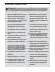
IMPORTANT PRECAUTIONS WARNING: To reduce the risk of burns, fire, electric shock, or injury to persons, read all important precautions and instructions in this manual and all warnings on your treadmill before using your treadmill. ICON assumes no responsibility for personal injury or property damage sustained by or through the use of this product. 1. It is the responsibility of the owner to ensure that all users of this treadmill are adequately informed of all warnings and precautions. 12.
able to safely lift 45 lbs. (20 kg) to move the treadmill. 19. Always stand on the foot rails when starting or stopping the walking belt. Always hold the handrails while using the treadmill. 20. When a person is walking on the treadmill, the noise level of the treadmill will increase. 26. When folding or moving the treadmill, make sure that the storage latch is holding the frame securely in the storage position. 21. Keep fingers, hair, and clothing away from the moving walking belt. 27.
STANDARD SERVICE PLANS all 5
BEFORE YOU BEGIN Thank you for selecting the new PROFORM® 505 CST treadmill. The 505 CST treadmill provides an impressive selection of features designed to make your workouts at home more effective and enjoyable. manual. To help us assist you, note the product model number and serial number before contacting us. The model number and the location of the serial number decal are shown on the front cover of this manual. For your benefit, read this manual carefully before you use the treadmill.
PART IDENTIFICATION CHART Use the drawings below to identify small parts used for assembly. The number in parentheses below each drawing is the key number of the part, from the PART LIST near the end of this manual. The number following the key number is the quantity used for assembly. Note: If a part is not in the hardware kit, check to see whether it is preattached. Extra parts may be included.
ASSEMBLY • To hire a service technician to assemble this product in your home, call 1-800-445-2480. • Left parts are marked “L” or “Left” and right parts are marked “R” or “Right.” • Assembly requires two persons. • To identify small parts, see page 7. • Place all parts in a cleared area and remove the packing materials. Do not dispose of the packing materials until you finish all assembly steps.
2. Make sure that the power cord is unplugged. 2 Remove the tie securing the Upright Wire (81) to the front of the Base (85). 81 A 81 Next, identify the Right Upright (90). Have a second person hold the Right Upright near the Base (85). 90 See the inset drawing. Tie the wire tie (A) in the Right Upright (90) securely around the end of the Upright Wire (81). Then, insert the Upright Wire into the lower end of the Right Upright as you pull the other end of the wire tie through the Right Upright.
4. Hold the Right Upright (90) against the Base (85). Make sure not to pinch the Upright Wire (81). 4 7 Attach the Right Upright (90) with two 3/8" x 2 3/8" Screws (7), a 3/8" x 1 1/4" Screw (51), a 3/8" x 1 3/4" Screw (62), and four 3/8" Star Washers (13) as shown; do not fully tighten the Screws yet. 13 Attach the Left Upright (not shown) in the same way. Note: There are no wires on the left side. 81 85 62 13 90 51 5. Identify the Left and Right Base Covers (82, 83).
6. Set a Handrail (84) on the Right Upright (90). Make sure that the Upright Wire (81) is not pinched. 6 28 Attach the Handrail (84) with two 5/16" x 2 1/4" Screws (28) and two 5/16" Star Washers (11); start both Screws, and then tighten them. 11 E 84 Attach the other Handrail (not shown) in the same way. Note: There is no wire on the left side. 81 Remove and discard the two indicated screws (E) from both Handrails (84) (only one side is shown). 7.
8. With the help of a second person, hold the console assembly (F) near the Right Handrail (84) and the Left Handrail (not shown). 8 F See the inset drawing. Connect the Upright Wire (81) to the console wire (G). The connectors should slide together easily and snap into place. If they do not, turn one connector and try again. IF YOU DO NOT CONNECT THE CONNECTORS PROPERLY, THE CONSOLE MAY BECOME DAMAGED WHEN YOU TURN ON THE POWER. Then, remove the wire tie (A) from the Upright Wire. G 81 84 G A 81 9.
10. IMPORTANT: To avoid damaging the Pulse Crossbar (5), do not use power tools and do not overtighten the #10 x 3/4" Screws (9). 10 Tighten four #10 x 3/4" Screws (9) with four 1/4" Star Washers (26) into the Pulse Crossbar (5) and the left and right Handrails (84); start all four Screws, and then tighten them. 9 26 See step 9. Tighten the four 1/4" x 1/2" Screws (2). 84 9 26 5 84 11. Identify the Left and Right Handrail Inserts (79, 31).
12. Identify the Left and Right Handrail Covers (87, 8). 12 Slide the Left Handrail Cover (87) up against the console assembly (F) and tighten a #8 x 3/4" Screw (4) into the bottom of the Left Handrail Cover. Be careful not to overtighten the Screw. F 87 Attach the Right Handrail Cover (8) in the same way. 4 8 4 13. Orient the Latch Pin Assembly (98) as shown.
14. Firmly tighten the four 3/8" x 2 3/8" Screws (7), the two 3/8" x 1 3/4" Screws (62), and the two 3/8" x 1 1/4" Screws (51). 14 89 Next, set the Left Inner Base Cover (97) onto the lower end of the Left Upright (89). Then, slide the Left Base Cover (82) downward and press it onto the Left Inner Base Cover. 82 Next, set the Right Inner Base Cover (96) onto the lower end of the Right Upright (90). Then, slide the Right Base Cover (83) downward and press it onto the Right Inner Base Cover.
HOW TO USE THE TREADMILL HOW TO CONNECT THE POWER CORD more amps. To avoid overloading the circuit, do not plug other electrical devices, except for lowpower devices such as cell phone chargers, into the surge suppressor or into an outlet on the same circuit. IMPORTANT: If the treadmill is connected to an AFCI-equipped outlet and your circuit breaker trips repeatedly when the treadmill is used, see the front cover of this manual to purchase an arc filter.
CONSOLE DIAGRAM FEATURES OF THE CONSOLE You can even listen to your favorite workout music or audio books with the console’s sound system while you exercise. The treadmill console offers a selection of features designed to make your workouts more effective and enjoyable. When you use the manual mode, you can change the speed and incline of the treadmill with the touch of a button. As you exercise, the console will display instant exercise feedback.
HOW TO TURN ON THE POWER HOW TO USE THE MANUAL MODE IMPORTANT: If the treadmill has been exposed to cold temperatures, allow it to warm to room temperature before you turn on the power. If you do not do this, you may damage the console displays or other electrical components. 1. Insert the key into the console. Plug in the power cord (see page 16). Next, locate the power switch on the treadmill frame near the power cord. Press the power switch into the reset position.
4. Change the incline of the treadmill as desired. The My Trail tab will show a track that represents 1/4 mile (400 m). As you exercise, the flashing rectangle will show your progress. The My Trail tab will also show the number of laps you complete. To change the incline of the treadmill, press the Incline increase or decrease button or one of the Quick Incline buttons. Each time you press one of the buttons, the treadmill will gradually adjust to the selected incline setting.
7. When you are finished exercising, remove the key from the console. 6. Measure your heart rate if desired. You can measure your heart rate using either the handgrip heart rate monitor or a compatible heart rate monitor. For information about purchasing an optional chest heart rate monitor, see page 22. When you are finished using the treadmill, step onto the foot rails, press the Stop button, and adjust the incline of the treadmill to zero.
Each workout is divided into segments. One speed setting and one incline setting are programmed for each segment. Note: The same speed setting and/ or incline setting may be programmed for consecutive segments.
HOW TO CONNECT YOUR SMART DEVICE TO THE CONSOLE THE OPTIONAL CHEST HEART RATE MONITOR Whether your goal is to burn fat or to strengthen your cardiovascular system, the key to achieving the best results is to maintain the proper heart rate during your workouts. The optional chest heart rate monitor will enable you to continuously monitor your heart rate while you exercise, helping you to reach your personal fitness goals. To purchase a chest heart rate monitor, please see the front cover of this manual. 1.
THE SETTINGS MODE HOW TO USE THE SOUND SYSTEM The console features an information mode that keeps track of treadmill information and allows you to personalize console settings. To play music or audio books through the console sound system while you exercise, plug a 3.5 mm male to 3.5 mm male audio cable (not included) into the jack on the console and into a jack on your personal audio player; make sure that the audio cable is fully plugged in.
FCC INFORMATION This console has been tested and found to comply with the limits for a Class B digital device, pursuant to part 15 of the FCC Rules. These limits are designed to provide reasonable protection against harmful interference in a residential installation. This equipment generates, uses, and can radiate radio frequency energy and, if not installed and used in accordance with the instructions, may cause harmful interference to radio communications.
HOW TO FOLD AND MOVE THE TREADMILL HOW TO FOLD THE TREADMILL HOW TO MOVE THE TREADMILL To avoid damaging the treadmill, adjust the incline to zero before you fold the treadmill. Then, remove the key and unplug the power cord. CAUTION: You must be able to safely lift 45 lbs. (20 kg) to raise, lower, or move the treadmill. Before moving the treadmill, fold it as described at the left. CAUTION: Make sure that the latch knob is locked in the storage position. Moving the treadmill may require two people. 1.
MAINTENANCE AND TROUBLESHOOTING c. Check the power switch located on the treadmill frame near the power cord. If the switch protrudes as shown, the switch has tripped. To reset the power switch, wait for five minutes and then press the switch back in. MAINTENANCE Regular maintenance is important for optimal performance and to reduce wear. Inspect and properly tighten all parts each time the treadmill is used. Regularly clean the treadmill and keep the walking belt clean and dry.
c. Your treadmill features a walking belt coated with high-performance lubricant. IMPORTANT: Never apply silicone spray or other substances to the walking belt or the walking platform unless instructed to do so by an authorized service representative. Such substances may deteriorate the walking belt and cause excessive wear. If you suspect that the walking belt needs more lubricant, see the front cover of this manual. SYMPTOM: The incline of the treadmill does not change correctly a.
b. If the walking belt slips when walked on, first remove the key and UNPLUG THE POWER CORD. Using the hex key, turn both idler roller screws clockwise, 1/4 of a turn. When the walking belt is correctly tightened, you should be able to lift each edge of the walking belt 2 to 3 in. (5 to 7 cm) off the walking platform. Be careful to keep the walking belt centered. Then, plug in the power cord, insert the key, and carefully walk on the treadmill for a few minutes.
EXERCISE GUIDELINES Burning Fat—To burn fat effectively, you must exercise at a low intensity level for a sustained period of time. During the first few minutes of exercise, your body uses carbohydrate calories for energy. Only after the first few minutes of exercise does your body begin to use stored fat calories for energy. If your goal is to burn fat, adjust the intensity of your exercise until your heart rate is near the lowest number in your training zone.
SUGGESTED STRETCHES The correct form for several basic stretches is shown at the right. Move slowly as you stretch—never bounce. 1. Toe Touch Stretch Stand with your knees bent slightly and slowly bend forward from your hips. Allow your back and shoulders to relax as you reach down toward your toes as far as possible. Hold for 15 counts, then relax. Repeat 3 times. Stretches: Hamstrings, back of knees and back. 1 2. Hamstring Stretch Sit with one leg extended.
PART LIST Key No. Qty. 1 2 3 4 5 6 7 8 9 10 11 12 13 14 15 16 17 18 19 20 21 22 23 24 25 26 27 28 29 30 31 32 33 34 35 36 37 38 39 40 41 42 43 44 45 46 47 48 49 50 51 52 10 4 2 45 1 2 4 1 4 8 4 4 8 8 3 1 2 1 4 2 2 2 4 2 1 10 1 4 1 4 1 2 6 4 4 1 6 2 4 2 1 1 1 1 1 2 1 4 1 6 2 2 Model No. PFTL60916.0 R0816A Description Key No. Qty.
15 4 59 30 34 23 66 39 14 93 32 4 40 37 43 61 50 4 57 44 15 35 66 39 14 93 41 50 1 4 40 37 23 42 4 46 35 47 50 37 59 30 34 45 19 30 50 35 56 37 34 60 59 21 102 23 49 37 50 35 10 53 93 66 39 14 55 37 94 20 48 19 15 54 59 30 34 93 46 50 23 102 66 39 14 21 10 53 10 73 95 10 24 EXPLODED DRAWING A Model No. PFTL60916.
EXPLODED DRAWING B Model No. PFTL60916.
EXPLODED DRAWING C Model No. PFTL60916.
EXPLODED DRAWING D Model No. PFTL60916.
ORDERING REPLACEMENT PARTS To order replacement parts, please see the front cover of this manual.