www.proform.com Model No. PFTL70011.2 Serial No. Write the serial number in the space above for reference. Serial Number Decal ACTIVATE YOUR WARRANTY To register your product and activate your warranty today, go to www.proformservice.com/ registration. CUSTOMER CARE For service at any time, go to www.proformservice.com. Or call 1-888-533-1333 Mon.–Fri. 6 a.m.–6 p.m. MT Sat. 8 a.m.–12 p.m. MT Please do not contact the store.
TABLE OF CONTENTS WARNING DECAL PLACEMENT . . . . . . . . . . . . . . . . . . . . . . . . . . . . . . . . . . . . . . . . . . . . . . . . . . . . . . . . . . . . . . .2 IMPORTANT PRECAUTIONS. . . . . . . . . . . . . . . . . . . . . . . . . . . . . . . . . . . . . . . . . . . . . . . . . . . . . . . . . . . . . . . . . . 3 BEFORE YOU BEGIN. . . . . . . . . . . . . . . . . . . . . . . . . . . . . . . . . . . . . . . . . . . . . . . . . . . . . . . . . . . . . . . . . . . . . . . .7 PART IDENTIFICATION CHART.
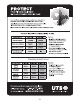
IMPORTANT PRECAUTIONS WARNING: To reduce the risk of burns, fire, electric shock, or injury to persons, read all important precautions and instructions in this manual and all warnings on your treadmill before using your treadmill. ICON assumes no responsibility for personal injury or property damage sustained by or through the use of this product. 1. It is the responsibility of the owner to ensure that all users of this treadmill are adequately informed of all warnings and precautions. 12.
25. Do not change the incline of the treadmill by placing objects under the treadmill. 20. The treadmill is capable of high speeds. Adjust the speed in small increments to avoid sudden jumps in speed. 26. Never insert any object into any opening on the treadmill. 21. The heart rate monitor is not a medical device. Various factors, including the user’s movement, may affect the accuracy of heart rate readings.
STANDARD SERVICE PLANS all 6
BEFORE YOU BEGIN Thank you for selecting the new PROFORM® CARDIO SMART treadmill. The CARDIO SMART treadmill provides an impressive selection of features designed to make your workouts at home more effective and enjoyable. reading this manual, please see the front cover of this manual. To help us assist you, note the product model number and serial number before contacting us. The model number and the location of the serial number decal are shown on the front cover of this manual.
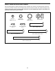
PART IDENTIFICATION CHART Use the drawings below to identify small parts used for assembly. The number in parentheses below each drawing is the key number of the part, from the PART LIST near the end of this manual. The number following the key number is the quantity used for assembly. Note: If a part is not in the hardware kit, check to see whether it is preattached. Extra parts may be included.
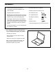
ASSEMBLY • To hire an authorized service technician to assemble your exercise equipment, call 1-800-445-2480. • To identify small parts, see page 8. • Assembly requires the following tools: • Assembly requires two persons. the included hex keys • Place all parts in a cleared area and remove the packing materials. Do not dispose of the packing materials until you finish all assembly steps.
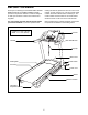
2. Make sure that the power cord is unplugged. 2 Locate the Upright Wire (70) bundled around the front of the Base (80). Cut the plastic tie securing the Upright Wire. Then, route the Upright Wire into the Base and out of the indicated hole. Press a Base Cap (77) into each side of the Base (80) (only one side is shown). See the inset drawing. Cut the plastic tie near the Upright Wire (70). Be careful not to damage the Upright Wire. 80 70 Cut Tie Hole 77 Cut 70 3.
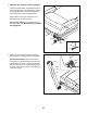
4. Hold the Left Upright (75) against the Base (80). Be careful not to pinch the wires. Partially tighten three 3/8" x 4" Screws (4) with three 3/8" Star Washers (5) into the Left Upright and the Base. Do not fully tighten the Screws yet. 4 75 Attach the Right Upright (not shown) in the same way. Note: There are no wires on the right side. 5 4 Wires 80 5. Identify the Left and Right Base Covers (73, 74). Slide the Left and Right Base Covers onto the Left and Right Uprights (75, 76) as shown.
6. Identify the left handrail assembly (A). If there is a wire in the Left Handrail, remove and discard it. 6 10 Hold the left handrail assembly (A) near the Left Upright (75). Insert the wire tie on the Upright Wire (70) into the bottom of the left handrail assembly and out of the end as shown. Then, pull the Upright Wire through the left handrail assembly. 70 8 B Attach the left handrail assembly (A) to the Left Upright (75) with two 5/16" x 2 3/4" Screws (10) and two 5/16" Star Washers (8).
8. Identify the Left and Right Trays (92, 35). 8 Attach the Trays (92, 35) to the Console Base (83) with eight #8 x 1/2" Screws (9). Note: It may be easier to start the two inside Screws and then slide the Trays into place before starting the other six Screws. 87 35 9 9 92 Note: It may be necessary to rotate the Console Frame (87) upward when attaching the Trays (92, 35). 9 83 9 9 9.
10. With the help of a second person, hold the console assembly near the left Handrail (71) and the right Handrail (not shown). 10 Console Assembly Connect the ground wire from the console assembly to the Console Ground Wire (89) on the Pulse Crossbar (31). See the inset drawing. Connect the Upright Wire (70) to the console wire. The connectors should slide together easily and snap into place. If they do not, turn one connector and try again.
12. Attach the Pulse Crossbar (31) to the console assembly with six #8 x 1/2" Screws (9). Start all six Screws, and then tighten them. 12 Console Assembly Firmly tighten the four 5/16" x 5/8" Screws (7). 7 7 31 9 13. Firmly tighten all six 3/8" x 4" Screws (4). Then, slide the Left and Right Base Covers (73, 74) down.
14. Raise the Frame (49) to the position shown. Have a second person hold the Frame until this step is completed. 14 Orient the Storage Latch (51) so that the large barrel and the latch knob are oriented as shown. 49 Attach the lower end of the Storage Latch (51) to the Base (80) with a 3/8" x 2" Bolt (12) and a 3/8" Nut (3). 3 12 Attach the upper end of the Storage Latch (51) to the Frame (49) with a 3/8" x 2" Bolt (12) and a 3/8" Nut (3). 51 Latch Knob Large Barrel 3 12 80 15.
HOW TO USE THE TREADMILL HOW TO CONNECT THE POWER CORD nominal 120-volt circuit capable of carrying 15 or more amps. To avoid overloading the circuit, do not plug other electrical devices, except for lowpower devices such as cell phone chargers, into the surge suppressor or into an outlet on the same circuit. IMPORTANT: The treadmill may not be compatible with AFCI-equipped outlets.
CONSOLE DIAGRAM FEATURES OF THE CONSOLE You can even listen to your favorite workout music or audio books with the console’s sound system while you exercise. The treadmill console offers an impressive array of features designed to make your workouts more effective and enjoyable. When you use the manual mode, you can change the speed and incline of the treadmill with the touch of a button. As you exercise, the console will display instant exercise feedback.
HOW TO TURN ON THE POWER HOW TO USE THE MANUAL MODE IMPORTANT: If the treadmill has been exposed to cold temperatures, allow it to warm to room temperature before you turn on the power. If you do not do this, you may damage the console displays or other electrical components. 1. Insert the key into the console. Plug in the power cord (see page 17). Next, locate the power switch on the treadmill frame near the power cord. Press the power switch into the reset position.
5. Follow your progress with the displays. To measure your heart rate, stand on the foot rails and hold the pulse bar with your palms on the contacts; Contacts avoid moving your hands. When your pulse is detected, several dashes will appear and then your heart rate will be shown. For the most accurate heart rate reading, continue to hold the contacts for about 15 seconds. The matrix—When you select the manual mode, the matrix will display a track that represents 1/4 mile (400 m).
HOW TO USE AN ONBOARD WORKOUT The workout will continue in this way until the last segment of the profile flashes in the display and the last segment ends. The walking belt will then slow to a stop. 1. Insert the key into the console. See HOW TO TURN ON THE POWER on page 19.
HOW TO USE THE WEIGHT LOSS CENTER 4. Follow your progress with the displays. 1. Insert the key into the console. See step 5 on page 20. See HOW TO TURN ON THE POWER on page 19. Note: The calorie goal is an estimate of the number of calories that you will burn during the workout. The actual number of calories that you burn will depend on various factors such as your weight.
HOW TO USE AN IFIT WORKOUT the button, the treadmill will automatically adjust to the first speed and incline settings of the workout. Hold the handrails and begin walking. To purchase iFit cards at any time, go to www.iFit.com or call the telephone number on the front cover of this manual. iFit cards are also available at select stores. During the workout, the voice of a personal trainer will guide you through the workout. 1. Insert the key into the console.
THE INFORMATION MODE An “E” for English miles or an “M” for metric kilometers will appear in the right display. Press the Speed increase button to change the unit of measurement if desired. The console features an information mode that keeps track of the total distance that the walking belt has moved and the total number of hours that the treadmill has been used. The information mode also allows you to select miles or kilometers to measure distance, and to turn on and turn off the display demo mode.
HOW TO FOLD AND MOVE THE TREADMILL HOW TO FOLD THE TREADMILL HOW TO MOVE THE TREADMILL To avoid damaging the treadmill, adjust the incline to zero before you fold the treadmill. Then, remove the key and unplug the power cord. CAUTION: You must be able to safely lift 45 lbs. (20 kg) to raise, lower, or move the treadmill. efore moving the treadmill, fold it as described at the B left. CAUTION: Make sure that the latch knob is locked in the storage position. Moving the treadmill may require two people.
MAINTENANCE AND TROUBLESHOOTING MAINTENANCE SYMPTOM: The power turns off during use Regularly clean the treadmill and keep the walking belt clean and dry. First, press the power switch into the off position and unplug the power cord. Wipe exterior parts of the treadmill with a damp cloth and a small amount of mild soap. IMPORTANT: Do not spray liquids directly onto the treadmill. To avoid damage to the console, keep liquids away from the console. Then, thoroughly dry the treadmill with a soft towel. a.
Lower the treadmill. Next, remove the indicated #8 x 3/4" Screws (6). Carefully slide the Motor Hood (57) off. 57 6 begin calibrating, press the Stop button again, and then press the Incline increase or decrease button again. When the incline is calibrated, remove the key from the console. SYMPTOM: The walking belt slows when walked on 6 6 a. Use only a surge suppressor that meets all of the specifications described on page 17. b.
SYMPTOM: The walking belt is off-center or slips when walked on b. If the walking belt slips when walked on, first remove the key and UNPLUG THE POWER CORD. Using the hex key, turn both idler roller screws clockwise, 1/4 of a turn. When the walking belt is correctly tightened, you should be able to lift each edge of the walking belt 2 to 3 in. (5 to 7 cm) off the walking platform. Be careful to keep the walking belt centered.
EXERCISE GUIDELINES Burning Fat—To burn fat effectively, you must exercise at a low intensity level for a sustained period of time. During the first few minutes of exercise, your body uses carbohydrate calories for energy. Only after the first few minutes of exercise does your body begin to use stored fat calories for energy. If your goal is to burn fat, adjust the intensity of your exercise until your heart rate is near the lowest number in your training zone.
SUGGESTED STRETCHES The correct form for several basic stretches is shown at the right. Move slowly as you stretch—never bounce. 1. Toe Touch Stretch Stand with your knees bent slightly and slowly bend forward from your hips. Allow your back and shoulders to relax as you reach down toward your toes as far as possible. Hold for 15 counts, then relax. Repeat 3 times. Stretches: Hamstrings, back of knees and back. 1 2. Hamstring Stretch Sit with one leg extended.
PART LIST Model No. PFTL70011.2 R0614A Key No. Qty. Description Key No. Qty.
14 32 53 26 30 32 36 19 94 25 56 30 38 19 32 36 19 94 52 39 30 14 93 19 40 41 93 30 25 37 24 30 26 30 42 28 3 30 93 32 36 94 26 27 44 12 94 23 30 36 93 19 43 54 45 19 50 32 19 16 1 46 30 51 24 48 30 41 47 27 42 28 26 49 48 3 16 12 EXPLODED DRAWING A Model No. PFTL70011.
EXPLODED DRAWING B Model No. PFTL70011.
EXPLODED DRAWING C Model No. PFTL70011.
EXPLODED DRAWING D Model No. PFTL70011.
ORDERING REPLACEMENT PARTS To order replacement parts, please see the front cover of this manual.