proform.com Model No. PFTL99518.0 Serial No. Write the serial number in the space above for reference. Serial Number Decal ACTIVATE YOUR WARRANTY To register your product and activate your warranty today, go to my.proform.com. CUSTOMER CARE For service at any time, go to proformservice.com. Or call 1-888-533-1333 Mon.–Fri. 6 a.m.–6 p.m. MT Sat. 8 a.m.–12 p.m. MT Please do not contact the store. CAUTION Read all precautions and instructions in this manual before using this equipment.
TABLE OF CONTENTS WARNING DECAL PLACEMENT . . . . . . . . . . . . . . . . . . . . . . . . . . . . . . . . . . . . . . . . . . . . . . . . . . . . . . . . . . . . . . . 2 IMPORTANT PRECAUTIONS . . . . . . . . . . . . . . . . . . . . . . . . . . . . . . . . . . . . . . . . . . . . . . . . . . . . . . . . . . . . . . . . . . 3 BEFORE YOU BEGIN. . . . . . . . . . . . . . . . . . . . . . . . . . . . . . . . . . . . . . . . . . . . . . . . . . . . . . . . . . . . . . . . . . . . . . . .
IMPORTANT PRECAUTIONS WARNING: To reduce the risk of burns, fire, electric shock, or injury to persons, read all important precautions and instructions in this manual and all warnings on your treadmill before using your treadmill. ICON assumes no responsibility for personal injury or property damage sustained by or through the use of this product. 1. It is the responsibility of the owner to ensure that all users of this treadmill are adequately informed of all warnings and precautions. 12.
able to safely lift 45 lbs. (20 kg) to move the treadmill. 19. Always stand on the foot rails when starting or stopping the walking belt. Always hold the handrails while using the treadmill. 26. When folding or moving the treadmill, make sure that the storage latch is holding the frame securely in the storage position. Do not operate the treadmill while it is folded. 20. When a person is walking on the treadmill, the noise level of the treadmill will increase. 21.
STANDARD SERVICE PLANS all 5
BEFORE YOU BEGIN Thank you for selecting the new PROFORM® PERFORMANCE 800 I treadmill. The PERFORMANCE 800 I treadmill provides an impressive selection of features designed to make your workouts at home more effective and enjoyable. reading this manual, please see the front cover of this manual. To help us assist you, note the product model number and serial number before contacting us. The model number and the location of the serial number decal are shown on the front cover of this manual.
PART IDENTIFICATION CHART Use the drawings below to identify small parts used for assembly. The number in parentheses below each drawing is the key number of the part, from the PART LIST near the end of this manual. The number following the key number is the quantity used for assembly. Note: If a part is not in the hardware kit, check to see whether it is preattached. Extra parts may be included.
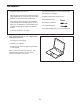
ASSEMBLY • Assembly requires two persons. • Left parts are marked “L” or “Left” and right parts are marked “R” or “Right.” • Place all parts in a cleared area and remove the packing materials. Do not dispose of the packing materials until you finish all assembly steps. • Assembly requires the following tools: the included hex keys • After shipping, there may be an oily substance on the exterior of the treadmill. This is normal.
2. Make sure that the power cord is unplugged. 2 80 A Remove the tie securing the Upright Wire (80) to the front of the Base (88). Next, identify the Right Upright (79). Have a second person hold the Right Upright near the Base (88). 80 79 See the inset drawing. Tie the wire tie (A) in the Right Upright (79) securely around the end of the Upright Wire (80). Then, insert the Upright Wire into the lower end of the Right Upright as you pull the other end of the wire tie through the Right Upright.
4. Set the Right Upright (79) on the Base (88) as shown. Make sure not to pinch the Upright Wire (80). Then, slide the Right Upright so that the 3/8" x 2 3/8" Screw (2) in the Base is inserted into the slot in the Right Upright. Do not tighten the Screw yet. 4 80 Slot 2 79 88 5. Attach the Right Upright (79) to the Base (88) with a 3/8" x 2 3/8" Screw (2), a 3/8" x 1 1/4" Screw (4), a 3/8" x 1 1/2" Screw (3), and three 3/8" Star Washers (6) as shown; do not fully tighten the Screws yet.
6. Remove and save the four indicated 5/16" x 3/4" Screws (13). 6 13 Identify the Left and Right Base Covers (94, 95). Slide the Left Base Cover onto the Left Upright (78), and slide the Right Base Cover onto the Right Upright (79). Do not press the Base Covers into place yet. 78 13 94 79 95 7. Attach a Handrail (72) to the Right Upright (79) with two 5/16" x 2" Screws (5) and two 5/16" Star Washers (7); start both Screws, and then tighten them. Make sure not to pinch the Upright Wire (80).
9. Set the Console Base (97) face down on a soft surface to avoid scratching the Console Base. 9 10 86 10 Remove and discard the two indicated screws (F). Then, remove the Pulse Crossbar (75). 10 Next, identify the Left and Right Trays (85, 86). Attach the Trays to the Console Base (97) with eight #8 x 1/2" Screws (10); do not overtighten the Screws. 85 10 13 Then, remove and save the four indicated 5/16" x 3/4" Screws (13). F 75 F 10.
11. With the help of a second person, hold the console assembly (G) near the Handrails (72). 11 G Connect the ground wires (H) from the console assembly (G) to the Console Ground Wires (76) on the Pulse Crossbar (75). Next, insert the Upright Wire (80) through the two indicated looped ties (I). J See the inset drawing. Connect the Upright Wire (80) to the console wire (J). The connectors should slide together easily and snap into place. If they do not, turn one connector and try again.
13. Attach the Pulse Crossbar (75) to the console assembly (G) with four #8 x 3/4" Screws (11); start all four Screws, and then tighten them. Do not overtighten the Screws. 13 G Firmly tighten the four 5/16" x 3/4" Screws (13). 75 13 13 11 11 14. Set the Left Handrail Cover (70) on the left Handrail (72). Start two #8 x 3/4" Screws (11) into the left Handrail and the Left Handrail Cover. Next, slide the Left Handrail Cover forward against the console assembly (G) as shown. Then, tighten both Screws.
. Raise the Frame (54) to the upright position. Have a second person hold the Frame until step 17 is completed. 15 Remove the two 5/16" x 3/4" Screws (13) from the Latch Crossbar (51). L Next, orient the Latch Crossbar (51) as shown. Make sure that the “This side toward belt” sticker (K) is facing the treadmill. Attach the Latch Crossbar to the brackets (L) on the Frame (54) with the two 5/16" x 3/4" Screws (13) that you just removed and two 5/16" Star Washers (7). 51 L 7 13 7 13 54 16.
17. Remove the 5/16" Nut (14) and the 5/16" x 2 1/4" Bolt (26) from the bracket on the Latch Crossbar (51). 17 14 N 51 26 Align the upper end of the Storage Latch (52) with the bracket on the Latch Crossbar (51), and insert the 5/16" x 2 1/4" Bolt (26) through the bracket and the Storage Latch. This will push a spacer (N) out of the Storage Latch; discard the spacer. 52 54 Next, tighten the 5/16" Nut (14) onto the 5/16" x 2 1/4" Bolt (26).
HOW TO USE THE TREADMILL HOW TO CONNECT THE POWER CORD more amps. To avoid overloading the circuit, do not plug other electrical devices, except for lowpower devices such as cell phone chargers, into the surge suppressor or into an outlet on the same circuit. IMPORTANT: If the treadmill is connected to an AFCI-equipped outlet and your circuit breaker trips repeatedly when the treadmill is used, see the front cover of this manual to purchase an arc filter.
CONSOLE DIAGRAM FEATURES OF THE CONSOLE In addition, the console features a selection of workouts. Each workout automatically controls the speed and incline of the treadmill as it guides you through an effective exercise session. The advanced treadmill console offers a selection of features designed to make your workouts more effective and enjoyable. You can even listen to your favorite workout music or audio books with the console’s sound system while you exercise.
HOW TO TURN ON THE POWER HOW TO USE THE TOUCH SCREEN IMPORTANT: If the treadmill has been exposed to cold temperatures, allow it to warm to room temperature before you turn on the power. If you do not do this, you may damage the console displays or other electrical components. The console features a tablet with a full-color touch screen. The following information will help you become familiar with the tablet’s advanced technology: Plug in the power cord (see page 17).
5. Check for firmware updates. HOW TO SET UP THE CONSOLE First, touch your name in the upper-left corner and touch the Settings button. Next, select the maintenance section. Then, touch the Update button to check for firmware updates using your wireless network. See HOW TO USE THE MAINTENANCE SECTION on page 26 for more information. Before using the treadmill for the first time, set up the console. 1. Connect to your wireless network.
HOW TO USE THE MANUAL MODE 4. Change the incline of the treadmill as desired. 1. Insert the key into the console. To change the incline of the treadmill, press the incline increase and decrease buttons or one of the numbered incline buttons. Each time you press one of the buttons, the incline will gradually change until it reaches the selected incline setting. See HOW TO TURN ON THE POWER on page 19. Note: It may take some time for the console to be ready for use. 2. Select the main menu.
• Your pace To measure your heart rate, stand on the foot rails and hold the contacts with your palms for approximately ten seconds; avoid moving your hands. When your pulse is detected, your heart rate will be shown. For the most accurate heart rate reading, continue to hold the contacts for about 15 seconds. • The speed of the walking belt • The average speed of the walking belt • A track representing 1/4 mile (400 m) If desired, adjust the volume by pressing the volume buttons on the console. 7.
HOW TO USE A MAP WORKOUT 5. Monitor your progress with the display modes. Note: To use a map workout, the console must be connected to a wireless network (see HOW TO USE THE WIRELESS NETWORK MODE on page 27). See step 5 on page 21. 6. Measure your heart rate if desired. 1. Insert the key into the console. See step 6 on page 22. See HOW TO TURN ON THE POWER on page 19. 7. Turn on the fan if desired. See step 7 on page 22. 2. Select the main menu or the workout library. 8.
HOW TO USE A DISTANCE OR TIME WORKOUT If you make a mistake, you can use the Undo button on the left side of the screen. Note: To use a distance or time workout, the console must be connected to a wireless network (see HOW TO USE THE WIRELESS NETWORK MODE on page 27). An iFit account is also required. The screen will display the elevation and distance statistics for your workout. If desired, you can change the default speed. 1. Add workouts to your schedule on iFit.com. 4. Save your workout.
HOW TO USE THE WORKOUT SETTINGS SECTION 5. Select a distance or time workout that you have previously added to your schedule on iFit.com. 1. Select the settings main menu. Touch the calendar icon to download a distance or time workout from your schedule. Insert the key into the console (see HOW TO TURN ON THE POWER on page 19). Then, touch your name in the upper-left corner of the screen, and touch the gears button to select the settings main menu.
HOW TO USE THE MAINTENANCE SECTION HOW TO USE THE EQUIPMENT SETTINGS SECTION 1. Select the settings main menu. 1. Select the settings main menu. See step 1 on page 25. See step 1 on page 25. 2. Select the maintenance section. 2. Select the equipment settings section. In the settings main menu, scroll to the Maintenance section. In the settings main menu, scroll to the Equipment Settings section. Note: Slide or flick the screen to scroll up or down through the options if necessary. 3.
HOW TO USE THE WIRELESS NETWORK MODE 4. Calibrate the incline system of the treadmill. The console features a wireless network mode that allows you to set up a wireless network connection. Touch the Calibrate Incline button. Then, touch the Begin button to calibrate the incline system. The treadmill will automatically rise to the maximum incline level, lower to the minimum incline level, and then return to the starting position. This will calibrate the incline system.
When the console is connected to your wireless network, a checkmark will appear next to the wireless network name. Then, touch the back button on the screen to return to the wireless network mode. THE OPTIONAL CHEST HEART RATE MONITOR Whether your goal is to burn fat or to strengthen your cardiovascular system, the key to achieving the best results is to maintain the proper heart rate during your workouts.
HOW TO FOLD AND MOVE THE TREADMILL HOW TO FOLD THE TREADMILL HOW TO MOVE THE TREADMILL To avoid damaging the treadmill, adjust the incline to zero before you fold the treadmill. Then, remove the key and unplug the power cord. CAUTION: You must be able to safely lift 45 lbs. (20 kg) to raise, lower, or move the treadmill. Before moving the treadmill, fold it as described at the left. CAUTION: Make sure that the storage latch is in the locked position. Moving the treadmill may require two people. 1.
MAINTENANCE AND TROUBLESHOOTING MAINTENANCE b. After the power cord has been plugged in, make sure that the key is inserted into the console. Regular maintenance is important for optimal performance and to reduce wear. Inspect and properly tighten all parts each time the treadmill is used. Replace any worn parts immediately. c. Check the power switch located on the treadmill frame near the power cord. If the switch protrudes as shown, the switch has tripped.
SYMPTOM: The incline of the treadmill does not change correctly c. Your treadmill features a walking belt coated with high-performance lubricant. IMPORTANT: Never apply silicone spray or other substances to the walking belt or the walking platform unless instructed to do so by an authorized service representative. Such substances may deteriorate the walking belt and cause excessive wear. If you suspect that the walking belt needs more lubricant, see the front cover of this manual. a.
SYMPTOM: The walking belt slips when walked on SYMPTOM: The displays of the console do not function properly a. First, remove the key and UNPLUG THE POWER CORD. Using the hex key, turn both idler roller screws clockwise, 1/4 of a turn. When the walking belt is correctly tightened, you should be able to lift each edge of the walking belt 2 to 3 in. (5 to 7 cm) off the walking platform. Be careful to keep the walking belt centered.
EXERCISE GUIDELINES Burning Fat—To burn fat effectively, you must exercise at a low intensity level for a sustained period of time. During the first few minutes of exercise, your body uses carbohydrate calories for energy. Only after the first few minutes of exercise does your body begin to use stored fat calories for energy. If your goal is to burn fat, adjust the intensity of your exercise until your heart rate is near the lowest number in your training zone.
SUGGESTED STRETCHES The correct form for several basic stretches is shown at the right. Move slowly as you stretch—never bounce. 1. Toe Touch Stretch Stand with your knees bent slightly and slowly bend forward from your hips. Allow your back and shoulders to relax as you reach down toward your toes as far as possible. Hold for 15 counts, then relax. Repeat 3 times. Stretches: Hamstrings, back of knees and back. 1 2. Hamstring Stretch Sit with one leg extended.
PART LIST Key No. Qty. 1 2 3 4 5 6 7 8 9 10 11 12 13 14 15 16 17 18 19 20 21 22 23 24 25 26 27 28 29 30 31 32 33 34 35 36 37 38 39 40 41 42 43 44 45 46 47 48 49 50 3 4 2 2 4 6 14 4 4 8 46 4 10 2 3 2 2 20 16 1 1 2 4 1 4 1 6 6 14 2 1 2 4 1 3 10 2 1 1 4 1 1 1 1 2 1 2 2 1 4 Model No. PFTL99518.0 R1118B Description Key No. Qty.
18 19 15 36 93 40 92 25 42 29 19 11 18 56 29 19 15 18 19 7 13 41 29 33 93 40 92 18 19 11 36 25 43 19 55 14 29 44 45 29 33 38 33 29 19 26 19 19 23 29 36 25 93 40 7 13 18 92 39 47 53 52 29 54 19 33 46 48 27 17 89 40 93 14 19 18 92 29 34 25 24 23 36 50 45 29 19 15 51 22 47 27 17 48 27 27 30 49 EXPLODED DRAWING A Model No. PFTL99518.
EXPLODED DRAWING B Model No. PFTL99518.
EXPLODED DRAWING C Model No. PFTL99518.
EXPLODED DRAWING D Model No. PFTL99518.
ORDERING REPLACEMENT PARTS To order replacement parts, please see the front cover of this manual.