www.proform.com Model No. PFTL20012.2 Serial No. Write the serial number in the space above for reference. Serial Number Decal ACTIVATE YOUR WARRANTY To register your product and activate your warranty today, go to www.proformservice.com/ registration. CUSTOMER CARE For service at any time, go to www.proformservice.com. Or call 1-888-533-1333 Mon.–Fri. 6 a.m.–6 p.m. MT Sat. 8 a.m.–12 p.m. MT Please do not contact the store.
TABLE OF CONTENTS WARNING DECAL PLACEMENT . . . . . . . . . . . . . . . . . . . . . . . . . . . . . . . . . . . . . . . . . . . . . . . . . . . . . . . . . . . . . . . 2 IMPORTANT PRECAUTIONS . . . . . . . . . . . . . . . . . . . . . . . . . . . . . . . . . . . . . . . . . . . . . . . . . . . . . . . . . . . . . . . . . . 3 BEFORE YOU BEGIN. . . . . . . . . . . . . . . . . . . . . . . . . . . . . . . . . . . . . . . . . . . . . . . . . . . . . . . . . . . . . . . . . . . . . . . .
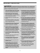
IMPORTANT PRECAUTIONS WARNING: To reduce the risk of burns, fire, electric shock, or injury to persons, read all important precautions and instructions in this manual and all warnings on your treadmill before using your treadmill. ICON assumes no responsibility for personal injury or property damage sustained by or through the use of this product. 1. It is the responsibility of the owner to ensure that all users of this treadmill are adequately informed of all warnings and precautions. 12.
20. The heart rate monitor is not a medical device. Various factors, including the user’s movement, may affect the accuracy of heart rate readings. The heart rate monitor is intended only as an exercise aid in determining heart rate trends in general. 24. Inspect and properly tighten all parts of the treadmill regularly. 25. DANGER: Always unplug the power cord immediately after use, before cleaning the treadmill, and before performing the maintenance and adjustment procedures described in this manual.
STANDARD SERVICE PLANS all 6
BEFORE YOU BEGIN Thank you for selecting the revolutionary PROFORM® PRO 9000 treadmill. The PRO 9000 treadmill offers an impressive selection of features designed to make your workouts at home more effective and enjoyable. reading this manual, please see the front cover of this manual. To help us assist you, please note the product model number and serial number before contacting us. The model number and the location of the serial number decal are shown on the front cover of this manual.
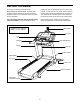
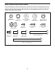
PART IDENTIFICATION CHART Use the drawings below to identify small parts used for assembly. The number in parentheses below each drawing is the key number of the part, from the PART LIST near the end of this manual. The number following the key number is the quantity used for assembly. Note: If a part is not in the hardware kit, check to see if it is preattached. Extra parts may be included.
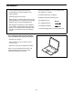
ASSEMBLY • To hire an authorized service technician to assemble your exercise equipment, call 1-800-445-2480. • Left parts are marked “L” or “Left” and right parts are marked “R” or “Right.” • To identify small parts, see page 8. • Assembly requires two persons. • Assembly requires the following tools: • Place all parts in a cleared area and remove the packing materials. Do not dispose of the packing materials until you nish all assembly steps.
2. Make sure that the power cord is unplugged. 2 78 Identify the Right Upright (81). Have a second person hold the Right Upright near the Frame (51). Wire Tie See the inset drawing. Tie the wire tie in the Right Upright (81) securely around the end of the Upright Wire (78). Then, pull the other end of the wire tie until the Upright Wire is routed through the Right Upright. 81 51 81 78 Wire Tie 3. Hold the Right Upright (81) against the Frame (51). Be careful not to pinch the wires.
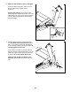
4. Hold the right handrail assembly (A) near the Right Upright (81). Insert the Upright Wire (78) into the large hole in the bottom of the right handrail, and pull it out of the front of the right handrail. 4 C B 78 10 3 Set the right handrail assembly (A) onto the Right Upright (81), and attach the right handrail with two 5/16" x 5/8" Screws (3) and two 5/16" Star Washers (10). Do not tighten the Screws yet. A 10 C 3 80 10 Attach the left handrail assembly (B) as described above.
6. Remove and discard the four indicated screws (D). Next, lift off the Pulse Bar Bottom (77). 6 3 Then, remove and discard the four 5/16" x 5/8" Screws (3). D D D 77 3 7. Set the Pulse Bar Bottom (77) onto the right and left handrail assemblies (A, B) as shown. If necessary, loosen the 3/8" x 2 3/4" Bolts (1) and the 3/8" x 4 1/4" Screws (2) (only one side is shown). 7 7 Attach the Pulse Bar Bottom (77) with four #10 x 3/4" Screws (7). Start all four Screws, and then tighten them.
8. With the help of a second person, hold the console assembly near the Right Upright (81) and the Left Upright (not shown). Insert the Upright Wire (78) through the looped plastic ties on the bottom of the console assembly. 8 Console Assembly Connect the Upright Wire (78) to the console wire. See the inset drawing. The connectors should slide together easily and snap into place. If they do not, turn one connector and try again.
10. Tighten four #8 x 3/4" Screws (5) into the bottom of the Pulse Bar Bottom (77). 10 5 11. Attach the console assembly with four 5/16" x 3/4" Screws (105), four 5/16" Flat Washers (103), and four 3/8" External Star Washers (104) as shown. Start all four Screws, and then tighten them. 11 77 5 5 Console Assembly Then, tighten the four 5/16" x 5/8" Screws (3).
12. Attach the Right Handrail Bottom (74) to the bottom of the right handrail assembly (A) with two #8 x 3/4" Screws (5). 12 B Attach the Left Handrail Bottom (73) to the bottom of the left handrail assembly (B) with two #8 x 3/4" Screws (5). A 5 73 74 13. Attach the Center Tray (79) to the tray brackets on the Right Upright (81) and the Left Upright (80) with four #8 x 3/4" Screws (5). Start all four Screws, and then tighten them.
14. Firmly tighten the 3/8" x 2 3/4" Bolt (1) and the 3/8" x 4 1/4" Screw (2) on each side of the treadmill (only one side is shown). 14 1 15. Identify the Right Outside Cover (83) and the Right Inside Cover (85). 2 15 Slide the Right Inside Cover (85) onto the bracket between the Motor Hood (59) and the Right Upright (81). 81 Press the Right Outside Cover (83) against the Right Inside Cover (85) and the Right Upright (81) until the two Covers snap together.
16. Slide the iPad Holder Cover (91) upward on the iPad Holder (92). Attach the iPad Holder to the console assembly with two 1/4" x 1/2" Screws (6). 16 6 Slide the iPad Holder Cover (91) down against the console assembly. 17. See HOW TO MOVE THE TREADMILL on page 33. Move the treadmill to the desired location. Console Assembly 92 91 17 Make sure that the leveling feet rest firmly on the floor.
THE CHEST HEART RATE MONITOR HOW TO PUT ON THE HEART RATE MONITOR The heart rate monitor consists of a chest strap and a sensor. Insert the tab on one end of the chest strap into the hole in one end of the sensor as shown. Then, press the end of the sensor under the buckle on the chest strap. The tab should be flush with the front of the sensor.
OPERATION AND ADJUSTMENT HOW TO CONNECT THE POWER CORD nominal 120-volt circuit capable of carrying 15 or more amps. To avoid overloading the circuit, do not plug other electrical devices, except for lowpower devices such as cell phone chargers, into the surge suppressor or into an outlet on the same circuit. IMPORTANT: The treadmill is not compatible with GFCI-equipped outlets and may not be compatible with AFCI-equipped outlets.
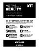
CONSOLE DIAGRAM MAKE YOUR FITNESS GOALS A REALITY WITH IFIT.COM FEATURES OF THE CONSOLE The advanced treadmill console offers an array of features designed to make your workouts more effective and enjoyable. With your new iFit-compatible fitness equipment, you can use an array of features on iFit.com to make your fitness goals a reality: When you use the manual mode, you can change the speed and incline of the treadmill with the touch of a button.
HOW TO TURN ON THE POWER HOW TO USE THE TOUCH SCREEN IMPORTANT: If the treadmill has been exposed to cold temperatures, allow it to warm to room temperature before you turn on the power. If you do not do this, you may damage the console displays or other electrical components. The console features a tablet with a full-color touch screen. The following information will help you become familiar with the tablet’s advanced technology: Plug in the power cord (see page 19).
HOW TO SET UP THE CONSOLE The browser will open to the iFit.com registration page. Fill in the information fields on the screen. Then, follow the prompts on the screen to sign up for your iFit membership. Before using the treadmill for the first time, set up the console. 1. Connect to your wireless network. The console is now ready for you to begin working out. The following pages explain the various workouts and other features that the console offers.
HOW TO USE THE MANUAL MODE the numbered % Grade buttons. Each time you press one of the buttons, the incline will gradually change until it reaches the selected incline setting. 1. Insert the key into the console. See HOW TO TURN ON THE POWER on page 21. Note: It may take a minute for the console to be ready for use. Note: The first time you adjust the incline, you must first calibrate the incline system (see step 4 on page 30). 2. Select the main menu. 5. Monitor your progress with the displays.
If desired, adjust the volume by pressing the volume increase and decrease buttons on the console. 7. Turn on the fan if desired. The fan features several speed settings and an auto mode. When the auto mode is selected, the speed of the fan will automatically increase and decrease as the speed of the walking belt increases and decreases. To pause the workout, touch one of the menu buttons or press the Stop button on the console. To continue the workout, touch the Resume button or the Start button.
HOW TO USE AN ONBOARD WORKOUT If the speed and/or incline settings are too high or too low at any time during the workout, you can override the settings by pressing the Speed or Incline buttons. If you press a Speed button, you can then manually control the speed (see step 3 on page 23). If you press an Incline button, you can then manually control the incline (see step 4 on page 23). To return to the programmed speed and/or incline settings of the workout, touch the Follow Workout button. 1.
HOW TO USE A SET-A-GOAL WORKOUT The workout will function in the same way as the manual mode (see pages 23 and 24). 1. Insert the key into the console. The workout will continue until you reach the goal that you set. The walking belt will then slow to a stop, and a workout summary will appear on the screen. After you view the workout summary, touch the Finish button to return to the main menu. You may also be able to either save or publish your results using one of the options on the screen.
HOW TO USE AN IFIT WORKOUT Before some workouts will download, you must add them to your schedule on iFit.com. Note: To use an iFit workout, you must have access to a wireless network (see HOW TO USE THE WIRELESS NETWORK MODE on page 31). An iFit account is also required. For more information about the iFit workouts, please see www.iFit.com. When you select an iFit workout, the screen will show the name, duration, and distance of the workout.
HOW TO USE THE EQUIPMENT SETTINGS MODE IMPORTANT: You must still unplug the power cord after using the treadmill. Set the update time for a time when you normally use the treadmill and will be available to unplug the power cord after an update. 1. Select the settings main menu. Insert the key into the console (see HOW TO TURN ON THE POWER on page 21). Next, select the main menu (see step 2 on page 23). Then, touch the gears button near the lowerright corner of the screen to select the settings main menu.
11. Enable or disable a passcode. 12. Set a safety screen timeout. The console features a child-safety passcode, designed to prevent unauthorized users from using the treadmill. The console features an automatic screen reset; if no buttons are touched or pressed and the walking belt does not move for a set amount of time, the console will automatically reset. Touch the Passcode button. To enable a passcode, touch the Enable checkbox. Then, enter a 4-digit passcode of your choice.
HOW TO USE THE MAINTENANCE MODE Note: Occasionally, a firmware update may cause your console to function slightly differently. These updates are always designed to improve your exercise experience. 1. Select the settings main menu. See step 1 on page 28. 4. Calibrate the incline system of the treadmill. 2. Select the maintenance mode. Touch the Calibrate Incline button. Then, touch the Begin button to calibrate the incline system.
HOW TO USE THE WIRELESS NETWORK MODE An information box will ask if you want to connect to the wireless network. Touch the Connect button to connect to the network or touch the Cancel button to return to the list of networks. If the network has a password, touch the password entry box. A keyboard will appear on the screen. To view the password as you type it, touch the Show Password checkbox. The console features a wireless network mode that allows you to set up a wireless network connection. 1.
HOW TO USE THE SOUND SYSTEM To use the keyboard, see HOW TO USE THE TOUCH SCREEN on page 21. To play music or audio books through the console sound system while you exercise, plug a 3.5 mm male to 3.5 mm male audio cable (not included) into the jack on the console and into a jack on your MP3 player, CD player, or other personal audio player; make sure that the audio cable is fully plugged in. Note: To purchase an audio cable, see your local electronics store.
HOW TO MOVE THE TREADMILL Due to the size and weight of the treadmill, moving it requires two or three persons. 2. After the treadmill is placed in the location where it will be used, make sure that the leveling feet rest firmly on the floor. If the treadmill rocks even slightly, loosen one of the nuts, turn the leveling foot clockwise or counterclockwise until the rocking motion is eliminated, and then retighten the nut.
TROUBLESHOOTING Most treadmill problems can be solved by following the simple steps below. Find the symptom that applies, and follow the steps listed. If further assistance is needed, see the front cover of this manual. SYMPTOM: The console displays remain lit when you remove the key from the console a. The console features a display demo mode, designed to be used if the treadmill is displayed in a store. If the screen shows a preset presentation when you remove the key, the demo mode is turned on.
SYMPTOM: The walking belt slows when walked on SYMPTOM: The walking belt is off-center or slips when walked on a. Use only a surge suppressor that meets all of the specifications described on page 19. a. If the walking belt is off-center, first remove the key and UNPLUG THE POWER CORD.
EXERCISE GUIDELINES Burning Fat—To burn fat effectively, you must exercise at a low intensity level for a sustained period of time. During the first few minutes of exercise, your body uses carbohydrate calories for energy. Only after the first few minutes of exercise does your body begin to use stored fat calories for energy. If your goal is to burn fat, adjust the intensity of your exercise until your heart rate is near the lowest number in your training zone.
SUGGESTED STRETCHES The correct form for several basic stretches is shown at the right. Move slowly as you stretch—never bounce. 1. Toe Touch Stretch Stand with your knees bent slightly and slowly bend forward from your hips. Allow your back and shoulders to relax as you reach down toward your toes as far as possible. Hold for 15 counts, then relax. Repeat 3 times. Stretches: Hamstrings, back of knees and back. 1 2. Hamstring Stretch Sit with one leg extended.
PART LIST Key No. Qty. 1 2 3 4 5 6 7 8 9 10 11 12 13 14 15 16 17 18 19 20 21 22 23 24 25 26 27 28 29 30 31 32 33 34 35 36 37 38 39 40 41 42 43 44 45 2 2 4 18 36 2 4 6 4 4 9 8 2 10 1 1 2 2 4 2 2 4 16 4 1 8 1 4 4 8 3 1 1 1 8 1 4 1 1 1 2 1 1 1 1 Model No. PFTL20012.2 R1013A Description Key No. Qty.
Key No. Qty. 91 92 93 94 95 96 97 98 1 1 1 4 1 1 1 1 Description Key No. Qty. iPad Holder Cover iPad Holder Console Frame Console Clamp Console Ground Wire Console Base Left Tray Right Tray 99 100 101 102 103 104 105 * 3 1 1 2 4 4 4 – Description Cable Tie Chest Strap Sensor 3/8" Wheel Washer 5/16" Flat Washer 3/8" External Star Washer 5/16" x 3/4" Screw User’s Manual Note: Specifications are subject to change without notice.
14 13 11 40 22 14 32 30 24 28 12 56 55 53 34 33 14 52 54 23 14 37 12 13 14 36 40 35 11 24 28 30 11 22 38 37 35 23 30 19 12 39 14 53 52 23 12 42 35 54 37 41 30 12 23 5 11 12 35 23 30 24 28 30 22 51 35 43 8 11 11 37 35 30 23 46 44 45 23 23 35 5 5 19 50 12 35 5 20 22 27 5 8 48 41 11 25 18 49 12 24 28 30 47 5 EXPLODED DRAWING A Model No. PFTL20012.
EXPLODED DRAWING B Model No. PFTL20012.
EXPLODED DRAWING C Model No. PFTL20012.
EXPLODED DRAWING D Model No. PFTL20012.
ORDERING REPLACEMENT PARTS To order replacement parts, please see the front cover of this manual.