With Universal Dock for iPod® www.proform.com Model No. PFTL49908.0 Serial No. Write the serial number in the space above for future reference. Serial Number Decal QUESTIONS? As a manufacturer, we are committed to providing complete customer satisfaction. If you have questions, or if parts are missing, DO NOT CONTACT THE STORE; please contact Customer Care.
TABLE OF CONTENTS WARNING DECAL PLACEMENT . . . . . . . . . . . . . . . . . . . . . . . . . . . . . . . . . . . . . . . . . . . . . . . . . . . . . . . . . . . . . .2 IMPORTANT PRECAUTIONS . . . . . . . . . . . . . . . . . . . . . . . . . . . . . . . . . . . . . . . . . . . . . . . . . . . . . . . . . . . . . . . .3 BEFORE YOU BEGIN . . . . . . . . . . . . . . . . . . . . . . . . . . . . . . . . . . . . . . . . . . . . . . . . . . . . . . . . . . . . . . . . . . . . . .5 ASSEMBLY . . . . . . . . . . . . .
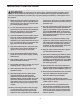
IMPORTANT PRECAUTIONS WARNING: To reduce the risk of serious injury, read all important precautions and instructions in this manual and all warnings on your treadmill before using your treadmill. ICON assumes no responsibility for personal injury or property damage sustained by or through the use of this product. 1. Before beginning any exercise program, consult your physician. This is especially important for persons over age 35 or persons with pre-existing health problems. carrying 15 or more amps.
23. Inspect and properly tighten all parts of the treadmill regularly. 19. Never leave the treadmill unattended while it is running. Always remove the key, unplug the power cord, and switch the reset/off circuit breaker to the off position when the treadmill is not in use. (See the drawing on page 5 for the location of the circuit breaker.) 24. 20. Do not attempt to raise, lower, or move the treadmill until it is properly assembled.
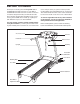
BEFORE YOU BEGIN Thank you for selecting the new PROFORM® 580 LT treadmill with Universal Dock for iPod®. The 580 LT treadmill with Universal Dock for iPod offers a selection of features designed to make your workouts at home more effective and enjoyable. And when youʼre not exercising, the treadmill can be folded up, requiring less than half the floor space of other treadmills. ual. To help us assist you, please note the product model number and serial number before contacting us.
ASSEMBLY To hire an authorized service technician to assemble the treadmill, call 1-800-445-2480. Assembly requires two persons. Set the treadmill in a cleared area and remove all packing materials. Do not dispose of the packing materials until assembly is completed. Note: The underside of the treadmill walking belt is coated with high-performance lubricant. During shipping, a small amount of lubricant may be transferred to the top of the walking belt or the shipping carton.
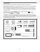
1. Make sure that the power cord is unplugged. 1 With the help of a second person, carefully tip the treadmill onto its left side. Partially fold the Frame (56) so that the treadmill is more stable; do not fully fold the Frame yet. 88 Remove and discard the two indicated bolts (B) and the shipping bracket (C). 2. Attach two Base Feet (92) to the Base (95) in the locations shown with two M4.2 x 25mm Tek Screws (3) and two Base Foot Spacers (94).
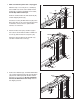
4. Identify the Right Upright (89) and the Right Upright Spacer (91), which are marked with stickers. 4 Insert the Wire Harness (88) through the Right Upright Spacer (91) as shown. Then, set the Right Upright Spacer on the Base (95). Long Tie 88 With the help of a second person, hold the Right Upright (89) near the Base (95). See the inset drawing. Tie the long tie in the Right Upright securely around the end of the Wire Harness (88).
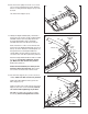
7. With the help of a second person, carefully tip the treadmill onto its right side. Partially fold the Frame (56) so that the treadmill is more stable; do not fully fold the Frame yet. 7 Remove and discard the two indicated bolts (B) and the shipping bracket (C). C B Remove the M10 Nut (19), the M10 x 50mm Bolt (31), and the shipping bracket (A) from the Base (95). Attach a Wheel (97) with the Bolt and the Nut that you just removed. Do not overtighten the Nut; the Wheel must turn freely.
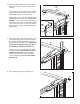
. Set the Console (105) face down on a soft surface to avoid scratching the Console. Remove the ties securing the Pulse Support (111) to the Console. 10 Lift off the Pulse Support (111). 105 111 11. Identify the Right Handrail (101), which has a large hole in the location shown. Hold the Right Handrail near the Console (105). Attach the Console Ground Wire (112) to the Right Handrail with a #8 x 1/2" Ground Screw (4).
13. Have a second person hold the console assembly near the Right Upright (89). Connect the Wire Harness (88) to the console wire. See the inset drawing. The connectors should slide together easily and snap into place. If they do not, turn one connector and try again. IF THE CONNECTORS ARE NOT CONNECTED PROPERLY, THE CONSOLE MAY BE DAMAGED WHEN THE POWER IS TURNED ON. Remove the long tie from the Wire Harness and the tie from the console wire. Then, insert the connectors into the Right Upright (89).
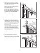
15. Raise the Frame (56) to the position shown. Have a second person hold the Frame until this step is completed. 15 Orient the Storage Latch (60) so that the large barrel and the Latch Knob (61) are in the positions shown. 56 7 6 Remove the tie from the upper end of the Storage Latch (60). Attach the upper end of the Storage Latch to the Frame (56) with a 3/8" x 1 3/4" Bolt (7) and a 3/8" Locknut (6). 60 61 Remove the tie from the lower end of the Storage Latch (60).
OPERATION AND ADJUSTMENT THE PRE-LUBRICATED WALKING BELT Your treadmill features a walking belt coated with highperformance lubricant. IMPORTANT: Never apply silicone spray or other substances to the walking belt or the walking platform. Such substances will deteriorate the walking belt and cause excessive wear. HOW TO PLUG IN THE POWER CORD DANGER: Improper connection of the equipment-grounding conductor can result in an increased risk of electric shock.
CONSOLE DIAGRAM Integrated Universal Dock for iPod Key Clip FEATURES OF THE CONSOLE certified by the developer to meet Apple performance standards. The treadmill console offers an impressive array of features designed to make your workouts more effective and enjoyable. To turn on the power, see page 15. To use the manual mode, see page 15. To use the weight loss center, see page 17. To use a classic workout, see page 18. To use the stereo sound system, see page 19.
HOW TO TURN ON THE POWER IMPORTANT: If the treadmill has been exposed to cold temperatures, allow it to warm to room temperature before turning on the power. If you do not do this, you may damage the console displays or other electrical components. Plug in the power cord (see page 13). Next, locate the reset/off circuit breaker on the treadmill frame near the power cord. Switch the circuit breaker to the reset position. HOW TO USE THE MANUAL MODE 1. Insert the key into the console.
4. Change the incline of the treadmill as desired. 6. Measure your heart rate if desired. Note: If you use the handgrip pulse sensor and the optional chest pulse sensor at the same time, the display will not show your heart rate accurately. See page 19 for information on the optional chest pulse sensor. To change the incline of the treadmill, press the Incline increase or decrease button. Each time you press the Incline increase or decrease button, the incline will change by 0.5%.
HOW TO USE THE WEIGHT LOSS CENTER buttons; however, when the next segment begins, the treadmill will automatically adjust to the speed and incline settings for the next segment. 1. Insert the key into the console. See HOW TO TURN ON THE POWER on page 15. To stop the workout at any time, press the Stop button. To restart the workout, press the Start button or the Speed increase button. The walking belt will begin to move at 1 mph.
HOW TO USE A CLASSIC WORKOUT incline setting will flash in the display for a moment to alert you. The treadmill will then automatically adjust to the speed and incline settings for the second segment. The arrow will then move one segment to the right. 1. Insert the key into the console. See HOW TO TURN ON THE POWER on page 15. 2. Select a classic workout. The workout will continue in this way until the arrow reaches the right end of the profile and the last segment ends.
HOW TO USE THE STEREO SOUND SYSTEM This product has been designed specifically to work with iPod and has been certified by the developer to meet Apple performance standards. To play music or audio books through the consoleʼs stereo speakers, you must connect your iPod, MP3 player, CD player, or other personal audio player to the console through the audio jack or through the Integrated Universal Dock for iPod.
HOW TO FOLD AND MOVE THE TREADMILL HOW TO FOLD THE TREADMILL FOR STORAGE Before folding the treadmill, adjust the incline to the lowest position. If you do not do this, you may damage the treadmill when you fold it. Remove the key and unplug the power cord. CAUTION: You must be able to safely lift 45 lbs. (20 kg) to raise, lower, or move the treadmill. 1. Hold the metal frame firmly in the location shown by the arrow at the right.
HOW TO LOWER THE TREADMILL FOR USE 1. Hold the upper end of the treadmill with your right hand. Pull the latch knob to the left and hold it. It may be necessary to push the frame forward as you pull the knob to the left. Pivot the frame downward and release the latch knob. Frame Latch Knob 2. Hold the metal frame firmly with both hands and lower it to the floor. CAUTION: Do not grip only the plastic foot rails or drop the frame to the floor. Bend your legs and keep your back straight.
TROUBLESHOOTING Most treadmill problems can be solved by following the steps below. Find the symptom that applies, and follow the steps listed. If further assistance is needed, please see the front cover of this manual. PROBLEM: The power does not turn on SOLUTION: a. Make sure that the power cord is plugged into a surge suppressor, and that the surge suppressor is plugged into a properly grounded outlet (see page 13).
Remove the three M4.2 x 19mm Hood Screws (12) and carefully pivot the Hood (67) off. 12 67 Locate the Reed Switch (70) and the Magnet (51) on the left side of the Pulley (53). Turn the Pulley until the Magnet is aligned with the Reed Switch. Make sure that the gap between the Magnet and the Reed Switch is about 1/8 in. (3 mm). If necessary, loosen the M4.2 x 19mm Screw (1), move the Reed Switch slightly, and then retighten the Screw. Reattach the Motor Hood (not shown) with the three M4.
PROBLEM: The walking belt is off-center or slips when walked on SOLUTION: a. If the walking belt is off-center, first remove the key and UNPLUG THE POWER CORD. If the walking belt has shifted to the left, use the hex key to turn the left idler roller bolt clockwise 1/2 of a turn; if the walking belt has shifted to the right, turn the bolt counterclockwise 1/2 of a turn. Be careful not to overtighten the walking belt. Then, plug in the power cord, insert the key, and run the treadmill for a few minutes.
EXERCISE GUIDELINES WARNING: Burning Fat—To burn fat effectively, you must exercise at a low intensity level for a sustained period of time. During the first few minutes of exercise, your body uses carbohydrate calories for energy. Only after the first few minutes of exercise does your body begin to use stored fat calories for energy. If your goal is to burn fat, adjust the intensity of your exercise until your heart rate is near the lowest number in your training zone.
PART LIST—Model No. PFTL49908.0 To locate the parts listed below, see the EXPLODED DRAWING near the end of this manual. Key No. Qty. 1 2 3 4 5 6 7 8 9 10 11 12 13 14 15 16 17 18 19 20 21 22 23 24 25 26 27 28 29 30 31 32 33 34 35 36 37 38 39 40 41 42 43 44 45 46 47 48 49 50 13 2 4 4 6 3 2 4 4 6 5 3 3 2 2 2 4 2 4 1 1 2 2 2 1 2 2 2 8 2 2 4 5 2 15 1 6 1 8 1 1 1 1 1 1 1 1 2 2 2 Description Key No. Qty. M4.2 x 19mm Screw M4 x 20mm Screw M4.
Key No. Qty. 101 102 103 104 105 106 107 108 109 110 1 3 1 1 1 1 1 1 1 1 Description Key No. Qty.
26 29 28 42 27 64 43 65 28 57 4 16 44 47 29 1 45 17 46 26 22 27 64 48 62 28 29 63 4 1 16 1 32 49 29 17 29 57 17 6 15 50 56 29 7 54 18 61 48 1 55 53 51 58 60 22 29 15 32 52 49 17 50 29 18 59 7 EXPLODED DRAWING A—Model No. PFTL49908.
EXPLODED DRAWING B—Model No. PFTL49908.
EXPLODED DRAWING C—Model No. PFTL49908.
EXPLODED DRAWING D—Model No. PFTL49908.
ORDERING REPLACEMENT PARTS To order replacement parts, please see the front cover of this manual.