
User's Manual
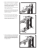

10. Set the Console (105) face down on a soft sur-
face to avoid scratching the Console. Remove
the ties securing the Pulse Support (111) to the
C
onsole.
L
ift off the Pulse Support (111).
1
0
105
111
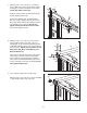
11. Identify the Right Handrail (101), which has a
large hole in the location shown. Hold the Right
Handrail near the Console (105). Attach the
Console Ground Wire (112) to the Right
Handrail with a #8 x 1/2" Ground Screw (4).
Next, insert the tie on the console wire into the
large hole in the Right Handrail (101) and out of
the top as shown. Insert the included plastic tie
through the holes in the Right Handrail as
shown. Make sure the plastic tie holds the con-
sole wire to the near side. Tighten the plastic tie.
Attach the Right Handrail with two M4.2 x 19mm
Screws (1); do not fully tighten the Screws
yet. Make sure that no wires are pinched.
Remove the plastic tie.
Attach the Left Handrail (not shown) to the
Console (105) in the same way. Note: There
are no wires on the left side of the Console.
101
Tie
11
1
1
Large
Hole
Console
Wire
Plastic Tie
112
105
4
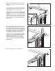
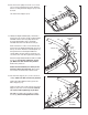
12. Set the Pulse Support (111) on the console as-
sembly. Make sure that no wires are pinched.
Tighten two M4 x 20mm Screws (2) into the
Pulse Support (111).
Tighten six #8 x 3/4" Screws (35) into the Pulse
Support (111) and console assembly. Start all
six Screws before tightening any of them.
See step 11. TIghten the four M4.2 x 19mm
Screws (1). Do not overtighten the Screws.
2
35
35
35
12
111
2
Console
Assembly
10