Model No. PFEL03907.0 Serial No. USER’S MANUAL Write the serial number in the space above for reference. Serial Number Decal QUESTIONS? As a manufacturer, we are committed to providing complete customer satisfaction. If you have questions, or if parts are damaged or missing, PLEASE DO NOT CONTACT THE STORE; please contact Customer Care. IMPORTANT: You must note the product model number and serial number (see the drawing above) before contacting us: CALL TOLL-FREE: 1-888-533-1333 Mon.–Fri. 6 a.m.–6 p.m.
TABLE OF CONTENTS WARNING DECAL PLACEMENT . . . . . . . . . . . . . . . . . . . . . . . . . . . . . . . . . . . . . . . . . . . . . . . . . . . . . . . . . . . . . .2 IMPORTANT PRECAUTIONS . . . . . . . . . . . . . . . . . . . . . . . . . . . . . . . . . . . . . . . . . . . . . . . . . . . . . . . . . . . . . . . .3 BEFORE YOU BEGIN . . . . . . . . . . . . . . . . . . . . . . . . . . . . . . . . . . . . . . . . . . . . . . . . . . . . . . . . . . . . . . . . . . . . . .4 ASSEMBLY . . . . . . . . . . . . . .
IMPORTANT PRECAUTIONS WARNING: To reduce the risk of serious injury, read all important precautions and instructions in this manual and all warnings on your elliptical exerciser before using your elliptical exerciser. ICON assumes no responsibility for personal injury or property damage sustained by or through the use of this product. 1. Before beginning any exercise program, consult your physician. This is especially important for persons over the age of 35 or persons with pre-existing health problems.
BEFORE YOU BEGIN Thank you for purchasing the revolutionary PROFORM® RAZOR X4 elliptical exerciser. The RAZOR X4 elliptical exerciser provides a wide array of features designed to make your workouts at home more effective and enjoyable. tacting us. The model number and the location of the serial number decal are shown on the front cover of this manual. To avoid a registration fee for any service needed under warranty, you must register the elliptical exerciser at www.proformservice.com/registration.
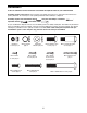
ASSEMBLY To hire an authorized service technician to assemble the elliptical exerciser, call 1-800-445-2480. Assembly requires two persons. Place all parts of the elliptical exerciser in a cleared area and remove the packing materials. Do not dispose of the packing materials until assembly is completed. Assembly requires the included hex keys and your own Phillips screwdriver adjustable wrench , and rubber mallet . , As you assemble the elliptical exerciser, use the drawings below to identify small parts.
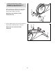
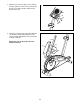
1. 1 To make assembly easier, read the information on page 5 before you begin assembling the elliptical exerciser. While another person lifts the rear of the Frame (1), attach a Frame Cover (48) to the Frame with two M4 x 16mm Screws (84). 48 Repeat this step to attach the other Frame Cover (48). 48 84 1 84 2. Attach a Wheel (50) to the front of the Frame (1) with an M10 x 35mm Shoulder Screw (63). 2 63 50 Repeat this step to attach the other Wheel (50).
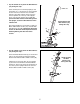
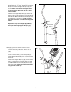
3. Tip: Be careful not to pinch the Wire Harness (49) during this step. 3 Wire Tie Have another person hold the Upright (2) near the Frame (1). Locate the wire tie in the Upright. Tie the lower end of the wire tie to the Wire Harness (49). Next, pull the upper end of the wire tie upward out of the top of the Upright. Then, untie and discard the wire tie. Tip: To prevent the Wire Harness from falling inside the Upright, secure the Wire Harness with a rubber band.
5. The Console (4) can be operated with four 1.5V “D” batteries (not included); alkaline batteries are recommended. IMPORTANT: If the elliptical exerciser has been exposed to cold temperatures, allow it to warm to room temperature before inserting batteries into the Console. If you do not do this, the console displays or other electronic components may become damaged. Remove the two screws from the back of the console, and remove the battery cover. Insert four batteries into the Console.
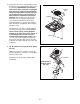
7. Slide the Console Cover (96) (see the drawing in step 6) upward to the Console (4). Attach the Console Cover with four M4 x 16mm Round Head Screws (94). 7 4 96 94 94 8. Attach the Left Pedal (12) to the left Pedal Arm (14) with three M10 x 70mm Button Screws (75), three M10 Split Washers (78), and an M4 x 16mm Screw (84). 8 14 Repeat this step on the right side of the elliptical exerciser.
9. Identify the Left Upper Body Arm (8), which is marked with an “L” sticker. Orient the Left Upper Body Arm and the left Upper Body Leg (6) as shown; make sure that the hexagonal holes in the Left Upper Body Arm are in the indicated location. 9 8 Slide the Left Upper Body Arm (8) onto the left Upper Body Leg (6). Attach the Left Upper Body Arm with two M6 x 36mm Button Bolts (76) and two M6 Nylon Locknuts (77); make sure that the Nylon Locknuts are inside the hexagonal holes.
. Apply a small amount of grease to a Pedal Arm Axle (21). While another person holds the right Pedal Arm (14) inside the bracket on the right Upper Body Leg (6), insert the Pedal Arm Axle through the Upper Body Leg and the Pedal Arm. 11 6 80 22 Then, tighten an M6 x 16mm Patch Screw (80) and an Axle Cover (22) into each end of the Pedal Arm Axle (21). Grease 21 22 80 Repeat this step for the other side of the elliptical exerciser. 14 12.
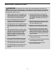
HOW TO USE THE ELLIPTICAL EXERCISER HOW TO MOVE THE ELLIPTICAL EXERCISER HOW TO EXERCISE ON THE ELLIPTICAL EXERCISER To move the elliptical exerciser, stand in front of it, place one foot against one of the wheels, and firmly hold the upper end of the upright. Pull the upright forward until you can move the elliptical exerciser on the wheels. Carefully move the elliptical exerciser to the desired location and then lower it to the floor.
HOW TO ADJUST THE STRIDE OF THE ELLIPTICAL EXERCISER Adjustment Pin To adjust the stride of the elliptical exerciser, first pull one of the adjustment knobs until the adjustment bracket pivots freely. Pivot the adjustment bracket until the adjustment knob is aligned with one of the two holes in the crank arm, and gently release the knob. Then, pivot the adjustment bracket back and forth slightly to make sure that the adjustment pin is engaged in one of the holes in the crank arm.
CONSOLE DIAGRAM FEATURES OF THE CONSOLE The console also offers six preset workouts. Each preset workout automatically changes the resistance of the pedals and prompts you to increase or decrease your pedaling pace as it guides you through an effective workout. The advanced console offers an array of features designed to make your workouts more effective and enjoyable. When you use the manual mode of the console, you can change the resistance of the pedals with the touch of a button.
HOW TO USE THE MANUAL MODE 4. Follow your progress with the displays. Note: If there is a sheet of clear plastic on the face of the console, remove the plastic. The lower left display—This display can show the elapsed time and the distance (total number of revolutions) that you have pedaled. 1. Press the decrease button or begin pedaling to turn on the console. When you turn on the console, the display will light and the console will be ready for use.
5. Measure your heart rate if desired. to move your hands excessively or to squeeze the metal contacts tightly. For optimal performance, clean the metal contacts using a soft cloth; never use alcohol, abrasives, or chemicals to clean the contacts. If there are sheets of clear plastic on the Contacts metal contacts on the handgrip pulse sensor, remove the plastic. In addition, make sure that your hands are clean.
HOW TO USE A PRESET WORKOUT 1. Turn on the console. See step 1 on page 15. If the resistance level for the current segment is too high or too low, you can manually override the setting by pressing the decrease and increase buttons. However, when the current segment ends, the pedals will automatically adjust to the resistance level for the next segment. 2. Select a preset workout.
MAINTENANCE AND TROUBLESHOOTING Inspect and tighten all parts of the elliptical exerciser regularly. Replace any worn parts immediately. until the console displays correct feedback. When the Reed Switch is correctly adjusted, reattach the side shields. Note: If you have questions as to which screw should be in which hole, see EXPLODED DRAWING B on page 23 and the PART LIST on page 20. To clean the elliptical exerciser, use a damp cloth and a small amount of mild soap.
EXERCISE GUIDELINES Burning Fat—To burn fat effectively, you must exercise at a low intensity level for a sustained period of time. During the first few minutes of exercise, your body uses carbohydrate calories for energy. Only after the first few minutes of exercise does your body begin to use stored fat calories for energy. If your goal is to burn fat, adjust the intensity of your exercise until your heart rate is near the lowest number in your training zone.
PART LIST—Model No. PFEL03907.0 Key No. Qty. 1 2 3 4 5 6 7 8 9 10 11 12 13 14 15 16 17 18 19 20 21 22 23 24 25 26 27 28 29 30 31 32 33 34 35 36 37 38 39 40 41 42 43 44 45 1 1 1 1 1 2 1 1 1 2 2 1 1 2 2 1 2 2 2 2 2 4 4 1 1 1 1 2 2 2 1 4 2 4 2 2 2 2 1 1 2 1 1 1 1 Description Key No. Qty.
Key No. Qty. 91 92 93 94 95 96 97 98 99 1 11 1 4 2 1 2 7 7 Description Key No. Qty. M4 x 63mm Screw M4 x 20mm Screw M4 x 35mm Screw M4 x 16mm Round Head Screw M4 x 32mm Screw Console Cover M8 x 18mm Button Screw M5 x 15mm Screw M4 x 12mm Screw 100 101 102 103 104 * * * 2 1 1 2 4 – – – Description M5 x 20mm Screw M4 x 45mm Screw M6 Washer M5 Washer M5 x 10mm Screw User’s Manual Hex Key Grease Packet Note: Specifications are subject to change without notice.
74 84 73 84 22 15 20 78 12 80 75 78 8 22 23 76 18 80 14 10 23 21 6 77 11 80 22 79 17 78 88 49 19 99 2 19 78 78 79 5 79 88 99 95 3 94 4 74 73 96 84 75 84 78 13 78 16 14 80 17 23 22 15 84 76 21 23 6 20 18 77 10 22 80 9 80 11 EXPLODED DRAWING A—Model No. PFEL03907.
34 92 44 34 32 92 91 35 32 47 100 48 36 33 97 93 30 37 31 92 29 87 92 92 28 41 26 92 41 69 7 98 103 39 98 38 84 99 103 104 83 55 83 90 99 83 90 83 90 24 54 71 1 51 46 38 65 40 66 57 58 56 59 85 99 53 70 64 63 52 42 74 25 72 74 85 50 68 29 60 87 67 82 61 102 62 45 30 101 27 50 47 92 81 28 97 34 92 33 35 32 34 43 37 63 100 48 92 36 32 EXPLODED DRAWING B—Model No. PFEL03907.
ORDERING REPLACEMENT PARTS To order replacement parts, please see the front cover of this manual.