Model No. 831.21822.3 Serial No. Write the serial number in the space above for reference. Serial Number Decal • Assembly • Operation • Maintenance • Part List and Drawing Sears, Roebuck and Co. Hoffman Estates, IL 60179 CAUTION Read all precautions and instructions in this manual before using this equipment. Keep this manual for future reference.
TABLE OF CONTENTS WARNING DECAL PLACEMENT . . . . . . . . . . . . . . . . . . . . . . . . . . . . . . . . . . . . . . . . . . . . . . . . . . . . . . . . . . . . . .2 IMPORTANT PRECAUTIONS . . . . . . . . . . . . . . . . . . . . . . . . . . . . . . . . . . . . . . . . . . . . . . . . . . . . . . . . . . . . . . . .3 BEFORE YOU BEGIN . . . . . . . . . . . . . . . . . . . . . . . . . . . . . . . . . . . . . . . . . . . . . . . . . . . . . . . . . . . . . . . . . . . . . .4 ASSEMBLY . . . . . . . . . . . . .
IMPORTANT PRECAUTIONS WARNING: To reduce the risk of serious injury, read all important precautions and instructions in this manual and all warnings on your exercise bike before using your exercise bike. Sears assumes no responsibility for personal injury or property damage sustained by or through the use of this product. 1. Before beginning any exercise program, consult your physician. This is especially important for persons over age 35 or persons with pre-existing health problems. 11.
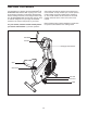
BEFORE YOU BEGIN Congratulations for selecting the new PROFORM® XP WHIRLWIND 280 exercise bike. Cycling is one of the most effective exercises for increasing cardiovascular fitness, building endurance, and toning the entire body. The XP WHIRLWIND 280 exercise bike offers an array of features designed to let you enjoy this healthful exercise in the comfort and privacy of your home. after reading this manual, please see the back cover of this manual.
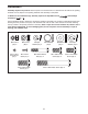
ASSEMBLY Assembly requires two persons. Place all parts of the exercise bike in a cleared area and remove the packing materials. Do not dispose of the packing materials until assembly is completed. In addition to the included tool(s), assembly requires an adjustable wrench screwdriver . and a Phillips See the drawings below to identify the small parts needed for assembly. The number in parentheses below each drawing is the key number of the part, from the PART LIST near the end of this manual.
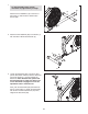
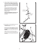
1. 1 To make assembly easier, read the information on page 5 before you begin. 19 Attach the Front Stabilizer (19) to the front of the Frame (1) with two M10 x 78mm Patch Screws (65). 1 2. Attach the Rear Stabilizer (60) to the Frame (1) with five M10 x 22mm Patch Screws (4). 2 4 60 1 4 4 3. Loosen the Seat Knob (29) a few turns. Next, pull the Seat Knob outward, insert the Seat Post (6) into the Frame (1), and then release the Seat Knob.
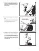
4. Attach the Seat (20) to the Seat Post (6) with four M8 Locknuts (66) and four M8 Split Washers (72). Note: The Locknuts and Split Washers may be preattached to the underside of the Seat. 4 20 6 72 66 5. Tip: To avoid pinching the Reed Switch Wire (31), position it as shown in the inset drawing. 5 Apply a small amount of the included grease to the Handlebar Axle (33). Insert the Handlebar Axle into the Frame (1) and center it. Grease 6.
7. The Console (3) requires four D batteries (not included); alkaline batteries are recommended. IMPORTANT: If the Console has been exposed to cold temperatures, allow it to warm to room temperature before inserting batteries. Otherwise, you may damage the console displays or other electronic components. Remove the battery cover and insert the batteries into the battery compartment. Make sure to orient the batteries as shown by the diagram inside the battery compartment. Then, reattach the battery cover.
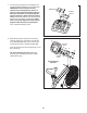
. Identify the Right Handlebar (9) and the Right Handlebar Base (10), which are marked with “Right” stickers. Orient these parts so that the wide side of the tube on the Right Handlebar and the Right Link Arm (16) are on the same side. 9 Attach the Right Handlebar (9) to the Right Handlebar Base (10) with two M6 x 38mm Button Bolts (57) and two M6 Locknuts (56). Make sure that the Locknuts are in the hexagonal holes.
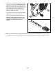
11. Remove the 1/2" Pedal Nut (68) from the shaft of one of the Pedals (23). See the lower drawing. Make sure that there is a Custom Washer (86), a Pedal Spring (42), a Blue Washer (71), a Pedal Bushing (43), a Black Pedal Washer (79), and a Pedal Spacer (44) on the shaft of the Pedal. In addition, make sure that the Pedal Bushing is oriented as shown. 11 Firmly tighten the shaft of the Pedal (23) clockwise into the right Crank Arm (26). Then, tighten the 1/2" Pedal Nut (68) onto the shaft.
HOW TO USE THE EXERCISE BIKE HANDLEBAR OPERATION Stationary Mode You can use the handlebars in the dual-action mode, for upper- and lower-body exercise, or in the stationary mode, for pedaling exercise only. To convert the handlebars to the stationary mode, the link arms must be disconnected from the pedals. Pull the link arms outward against the blue washers until the link arms are free of the pedal bushings (see drawing 2 at the left). Be careful not to pinch your fingers.
CONSOLE DIAGRAM HOW TO USE THE CONSOLE The lower right display can show your pedaling speed (in miles or kilometers per hour) and the approximate number of calories you have burned. When you use the handgrip pulse sensor, the lower right display will also show your heart rate (see step 3 on page 13). Before using the console, make sure that batteries are installed (see assembly step 7 on page 8). If there is a sheet of plastic on the display, remove the plastic.
The right display will show a track that represents 1/4 mile (400 meters). As you exercise, indicators will appear in succession around the track until the entire track appears. The track will then disappear and the indicators will again begin to appear in succession. When your pulse is detected, the heartshaped indicator in the lower right display will flash and one or two dashes will appear. After a moment, your heart rate will be shown in the display.
MAINTENANCE AND TROUBLESHOOTING Inspect and tighten all parts of the exercise bike regularly. To clean the exercise bike, use a damp cloth and a small amount of mild detergent; never use abrasives or solvents to clean the exercise bike. To avoid damaging the console, keep liquid away from the console. If the Belt (22) needs to be adjusted, first loosen the right Guard Fastener (not shown). To tighten the Belt, turn the M6 Nuts (53) clockwise; to loosen the Belt, turn the M6 Nuts counterclockwise.
ADJUSTING THE REED SWITCH Next, locate the Reed Switch (31). Turn the Crank Arm (26) until the Magnet (48) is aligned with the Reed Switch. If the console does not display correct feedback, the reed switch should be adjusted. To adjust the reed switch, the Right Shield (18) must be moved. Remove the four M4 x 25mm Screws (69) from the Right Shield. Lift the Right Link Arm (16) off the pedal or the lock rod and move it clear of the Right Shield.
EXERCISE GUIDELINES WARNING: Burning Fat—To burn fat effectively, you must exercise at a low intensity level for a sustained period of time. During the first few minutes of exercise, your body uses carbohydrate calories for energy. Only after the first few minutes of exercise does your body begin to use stored fat calories for energy. If your goal is to burn fat, adjust the intensity of your exercise until your heart rate is near the lowest number in your training zone.
SUGGESTED STRETCHES The correct form for several basic stretches is shown at the right. Move slowly as you stretch—never bounce. 1. Toe Touch Stretch 1 Stand with your knees bent slightly and slowly bend forward from your hips. Allow your back and shoulders to relax as you reach down toward your toes as far as possible. Hold for 15 counts, then relax. Repeat 3 times. Stretches: Hamstrings, back of knees and back. 2. Hamstring Stretch 2 Sit with one leg extended.
PART LIST Key No. Qty. 1 2 3 4 5 6 7 8 9 10 11 12 13 14 15 16 17 18 19 20 21 22 23 24 25 26 27 28 29 30 31 32 33 34 35 36 37 38 39 40 41 42 43 44 1 1 1 5 1 1 1 1 1 1 2 2 1 1 1 1 1 1 1 1 4 1 2 2 1 2 1 1 1 2 1 1 1 6 2 1 2 2 1 1 2 2 2 2 Description Key No. Qty.
EXPLODED DRAWING 53 38 53 38 35 11 58 8 24 45 73 57 73 15 22 78 59 66 23 52 74 2 80 55 55 54 54 19 21 64 40 63 75 41 42 86 71 67 79 25 48 72 82 81 47 66 83 72 72 66 6 20 50 70 34 66 73 69 26 28 69 19 84 85 34 10 73 67 57 58 24 23 41 50 4 4 21 69 60 4 69 72 49 45 16 86 39 71 79 44 68 42 43 1 18 17 34 56 83 62 30 69 68 44 26 43 46 72 48 81 77 66 28 31 32 29 62 21 78 33 30 27 34 11 9 61 77 55 12 14 36 5 12 34 34 5
Get it fixed, at your home or ours! Your Home For repair—in your home—of all major brand appliances, lawn and garden equipment, or heating and cooling systems, no matter who made it, no matter who sold it! For the replacement parts, accessories, and user’s manuals that you need to do-it-yourself. For Sears professional installation of home appliances and items like garage door openers and water heaters. 1-800-4-MY-HOME® (1-800-469-4663) Call anytime, day or night (U.S.A. and Canada) www.sears.com www.