www.proform.com Model No. PFEL05813.0 Serial No. Write the serial number in the space above for reference. Serial Number Decal (under frame) ACTIVATE YOUR WARRANTY To register your product and activate your warranty today, go to www.proformservice.com/ registration. CUSTOMER CARE For service at any time, go to www.proformservice.com. Or call 1-888-533-1333 Mon.–Fri. 6 a.m.–6 p.m. MT Sat. 8 a.m.–12 p.m. MT Please do not contact the store.
TABLE OF CONTENTS WARNING DECAL PLACEMENT . . . . . . . . . . . . . . . . . . . . . . . . . . . . . . . . . . . . . . . . . . . . . . . . . . . . . . . . . . . . . . . 2 IMPORTANT PRECAUTIONS . . . . . . . . . . . . . . . . . . . . . . . . . . . . . . . . . . . . . . . . . . . . . . . . . . . . . . . . . . . . . . . . . . 3 BEFORE YOU BEGIN. . . . . . . . . . . . . . . . . . . . . . . . . . . . . . . . . . . . . . . . . . . . . . . . . . . . . . . . . . . . . . . . . . . . . . . .
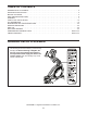
IMPORTANT PRECAUTIONS WARNING: To reduce the risk of serious injury, read all important precautions and instructions in this manual and all warnings on your elliptical before using your elliptical. ICON assumes no responsibility for personal injury or property damage sustained by or through the use of this product. 1. It is the responsibility of the owner to ensure that all users of the elliptical are adequately informed of all precautions. 9.
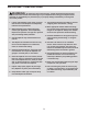
STANDARD SERVICE PLANS all 4
BEFORE YOU BEGIN Thank you for selecting the revolutionary PROFORM® ZE 6 elliptical. The ZE 6 elliptical provides an impressive selection of features designed to make your workouts at home more effective and enjoyable. manual. To help us assist you, note the product model number and serial number before contacting us. The model number and the location of the serial number decal are shown on the front cover of this manual. For your benefit, read this manual carefully before you use the elliptical.
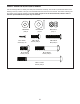
PART IDENTIFICATION CHART Use the drawings below to identify the small parts needed for assembly. The number in parentheses below each drawing is the key number of the part, from the PART LIST near the end of this manual. The number following the key number is the quantity needed for assembly. Note: If a part is not in the hardware kit, check to see if it has been preassembled. Extra parts may be included.
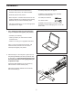
ASSEMBLY • To hire an authorized service technician to assemble this product, call 1-800-445-2480. • To identify small parts, see page 6. • In addition to the included tool(s), assembly requires the following tools: • Assembly requires two persons. • Place all parts in a cleared area and remove the packing materials. Do not dispose of the packing materials until you nish all assembly steps.
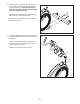
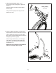
3. With the help of a second person, place some of the packing materials (not shown) under the front of the Frame (1). Have the second person hold the Frame to prevent it from tipping while you complete this step. 3 104 3 Attach the Front Stabilizer (3) to the Frame (1) with two M10 x 115mm Screws (104). Remove the packing materials from under the front of the Frame (1). 1 4. Orient the Upright (4) and the Upright Cover (23) as shown. Slide the Upright Cover upward onto the Upright.
5. Tip: Avoid pinching the wires. Have a second person hold the Upright (4) against the Frame (1). 5 Avoid pinching the wires Attach the Upright (4) with four M10 x 60mm Screws (106). Then, press the Upright Cover (23) onto the Shield Cover (30). 106 23 4 30 1 6. Identify the Right Upper Body Leg (26) and the Right Pedal Arm (37) and orient them as shown. 6 Using a plastic bag to keep your fingers clean, apply some of the included grease to the axle on the Right Upper Body Leg (26).
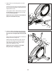
7. Apply some of the included grease to an Arm Axle (93). 7 Insert the Arm Axle (93) into the Right Pedal Arm (37), through an Arm Spacer (120), and into the Right Roller Arm (39). Then, tighten an M10 x 20mm Screw (107) with an M10 Washer (111) into each end of the Arm Axle (93) at the same time. 38 107 Repeat this step to attach the Left Pedal Arm (38) to the Left Roller Arm (40). 111 39 120 40 93 37 Grease 111 107 8. Identify the Right Upper Body Arm (25) and orient it as shown.
9. Insert the Right Upper Body Arm (25) into the Right Upper Body Leg (26). 9 Attach the Right Upper Body Arm (25) with two M8 x 38mm Bolts (108) and two M8 Locknuts (110). Make sure that the Locknuts are in the hexagonal holes. 27 Repeat this step to attach the Left Upper Body Arm (27) to the Left Upper Body Leg (not shown). 25 110 Hexagonal Holes 26 108 10. Identify an Upper Body Cover A (31) and an Upper Body Cover B (32) and orient them as shown.
. While a second person holds the Console (8) near the Upright (4), connect the Console wires to the Upper Wire (116) and the Pulse Wire (117). 12 8 Avoid pinching the wires Insert the excess wire into the Upright (4). 116 Tip: Avoid pinching the wires. Attach the Console (8) to the Upright (4) with four M4 x 16mm Screws (97). 4 117 13. Apply a small amount of the included PTFE grease to a paper towel.
HOW TO USE THE ELLIPTICAL HOW TO PLUG IN THE POWER ADAPTER HOW TO LEVEL THE ELLIPTICAL IMPORTANT: If the elliptical has been exposed to cold temperatures, allow it to warm to room temperature before you plug in the power adapter. If you do not do this, you may damage the console displays or other electronic components. If the elliptical rocks slightly on your floor during use, turn one or both of the leveling feet beneath the rear of the frame until the rocking motion is eliminated.
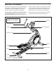
HOW TO EXERCISE ON THE ELLIPTICAL To mount the elliptical, hold the handlebars or the upper body arms and step onto the pedal that is in the lower position. Then, step onto the other pedal. Push the pedals until they begin to move with a continuous motion. Note: The pedals can turn in either direction. It is recommended that you turn the pedals in the direction shown by the arrow; however, for variety, you can turn the pedals in the opposite direction.
CONSOLE DIAGRAM FEATURES OF THE CONSOLE The console also offers a selection of preset workouts. Each preset workout automatically changes the resistance of the pedals as it guides you through an effective workout. The advanced console offers an array of features designed to make your workouts more effective and enjoyable. You can even connect your MP3 player or CD player to the console sound system and listen to your favorite music or audio books while you exercise.
HOW TO USE THE MANUAL MODE 4. Follow your progress with the display. 1. Turn on the console. The left display—This display can show the elapsed time and the approximate number of calories you have burned. The display will change modes every few seconds. Press any button or begin pedaling to turn on the console. When you turn on the console, the display will turn on. A tone will sound and the console will be ready for use.
5. Measure your heart rate if desired. If your heart rate is not shown, make sure that your hands are positioned as described. Be careful not to move your hands excessively or to squeeze the contacts tightly. For optimal performance, clean the contacts using a soft cloth; never use alcohol, abrasives, or chemicals to clean the contacts. If there are sheets of plastic on the metal contacts on the handgrip heart rate monitor, remove the plastic. In addition, make sure Contacts that your hands are clean.
HOW TO USE A PRESET WORKOUT The resistance level for the next segment will appear in the center display for a few seconds to alert you. The resistance of the pedals will then change. 1. Turn on the console. Press any button or begin pedaling to turn on the console. The target speed for the next segment will appear in the right display for a few seconds to alert you. 2. Select a preset workout. As you exercise, keep your pedaling speed near the target speed for the current segment.
HOW TO USE THE SOUND SYSTEM To select the settings mode, press and hold down the Performance Workouts button for a few seconds until the settings information appears in the display. To play music or audio books through the console sound system while you exercise, plug a 3.5 mm male to 3.5 mm male audio cable (not included) into the jack on the console and into a jack on your MP3 player, CD player, or other personal audio player; make sure that the audio cable is fully plugged in.
MAINTENANCE AND TROUBLESHOOTING Inspect and tighten all parts of the elliptical regularly. Replace any worn parts immediately. See the drawing below. Remove the M8 x 14mm Shoulder Screw (89), the Roller Arm Cover (58), and the M8 Washer (not shown) from the Left Roller Arm (40). To clean the elliptical, use a damp cloth and a small amount of mild soap. IMPORTANT: To avoid damage to the console, keep liquids away from the console and keep the console out of direct sunlight.
Next, locate the Reed Switch (60). Turn the Pulley (52) until a Magnet (86) is aligned with the Reed Switch. See assembly step 10 on page 11. Remove the Upper Body Covers A and B (31, 32) from the Right Upper Body Arm (25). See assembly step 9 on page 11. Remove the Right Upper Body Arm (25) from the Right Upper Body Leg (26). See EXPLODED DRAWING C on page 27 and EXPLODED DRAWING B on page 26.
EXERCISE GUIDELINES Burning Fat—To burn fat effectively, you must exercise at a low intensity level for a sustained period of time. During the first few minutes of exercise, your body uses carbohydrate calories for energy. Only after the first few minutes of exercise does your body begin to use stored fat calories for energy. If your goal is to burn fat, adjust the intensity of your exercise until your heart rate is near the lowest number in your training zone.
PART LIST Key No. Qty. 1 2 3 4 5 6 7 8 9 10 11 12 13 14 15 16 17 18 19 20 21 22 23 24 25 26 27 28 29 30 31 32 33 34 35 36 37 38 39 40 41 42 43 44 45 46 47 48 49 50 1 1 1 1 1 1 1 1 2 1 1 1 1 1 1 1 1 1 1 1 6 2 1 2 1 1 1 1 2 1 2 2 1 1 1 1 1 1 1 1 1 1 1 1 1 1 4 2 2 2 Model No. PFEL05813.0 R1213A Description Key No. Qty.
Key No. Qty. 101 102 103 104 105 106 107 108 109 110 111 112 113 2 2 8 4 2 4 6 4 2 6 6 1 1 Description Key No. Qty.
88 25 20 103 81 80 33 13 10 11 95 100 97 80 90 97 88 47 100 83 15 94 84 83 103 97 14 46 48 63 100 27 91 97 38 40 18 82 83 96 83 72 17 91 97 16 24 19 32 43 28 31 44 8 7 9 5 97 119 118 9 119 118 97 97 4 65 6 23 97 106 EXPLODED DRAWING A Model No. PFEL05813.
104 2 12 95 29 97 97 95 81 56 21 115 36 81 85 97 98 97 112 74 1 69 59 97 50 73 71 34 101 87 70 97 110 87 97 62 75 21 113 97 55 99 110 76 77 78 98 114 97 59 68 60 66 61 55 67 86 54 53 3 86 97 59 116 74 102 104 79 79 51 52 21 22 117 73 71 101 50 69 70 105 EXPLODED DRAWING B Model No. PFEL05813.
97 97 97 98 97 88 103 85 85 27 47 111 29 107 97 48 97 35 55 55 55 92 47 120 39 57 30 92 121 45 57 103 37 58 89 32 25 55 49 93 108 97 24 111 107 42 97 26 109 103 64 110 65 97 31 64 41 111 107 EXPLODED DRAWING C Model No. PFEL05813.
ORDERING REPLACEMENT PARTS To order replacement parts, please see the front cover of this manual.