Acute2 manual Profoto, Stockholm, Sweden.
Warning Profoto generators and lamp heads are parts of a complete professional lighting system. Please read the instruction manual carefully before use. Flash tubes and modelling lamps emit considerable heat and may cause injury if not handled properly. Note, always unplug the lamp cable from the generator before changing the modelling lamp or flash tube. • Under no circumstances are generators or heads to be opened.High voltage is inside the equipment. • Do not touch hot metal parts.
Contents Thanks! . . . . . . . . . . . . . . . . . . . . . . . . . . . . . . . . . . . . 4 The Acute2 System Chart . . . . . . . . . . . . . . . . . . . . . . . 6 Acute2 head . . . . . . . . . . . . . . . . . . . . . . . . . . . . . . . . 8 Acute2 twin . . . . . . . . . . . . . . . . . . . . . . . . . . . . . . . . . 9 The flash heads . . . . . . . . . . . . . . . . . . . . . . . . . . . . . . 10 Acute2 head . . . . . . . . . . . . . . . . . . . . . . . . . . . . . . . . 11 Acute2 twin . . . . . . . . . . .
Thanks! Thanks for showing us your confidence by investing in an Acute2 system. For more than three decades we have sought the perfect light. What pushes us is the conviction that we can offer even the most demanding photographer yet better tools. Before our products are shipped we have them pass an extensive and strict testing program. We check that they pass the quality and capacity levels the most demanding photographers require.
Profotos founders Eckhard Heine och Conny Dufgran, At ”Photokina”,Cologne, Germany 1968 ”A photographer’s tools are a natural part of the creative process. Like a painter’s brush, an artist’s chisel or a musician’s instrument, their form and design should reflect their function, they should have the right feel, and they should be aesthetically pleasing”.
Acute 2 Acute2 1200 Acute2 2400 Acute2 Flash Extension Cable Acute2 head Acute2 twin Narrow Beam travel Reflector Softlight Reflector Silver Softlight Reflector white ProGlobe w/clips Honeycomb Grid Glass Kit ProGlobe w/Chimera Disc Reflector Adapter Plate 5 and 7 foot Reflector ProZoom ProFocus ProBox ProFresnel White Pattern Holder & Pin Set 6 Heat absorbing Iris filter Diaphragm 60x60 Slide holders 24x36 Barn Doors for ProFresnel Transparent Silver
ProGas Power Cable Acute2 ring Close-up Reflector Softlight Reflector Narrow Beam travel Reflector Zoom Reflector 7” Grid Reflector Barn Doors Narrow Beam Reflector 13” Bell Reflector Magnum Reflector 7” Grid Pro Tube FilterHolder 40x40 cm Grid & Filter Holder 10° Honeycomb Grid BarnDoor The Acute2 series The system chart shows how the wide Profoto line of accessories fit together with generators Filter Cassette Snoot 5°, 10° & 20° Grid and heads.
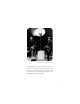
Acute2 head 1. UV reduced flash tube 2. Umbrella holder 3. Manoeuvre system with locking lever 4. Stand adapter 16mm (5/8") 5. Acute2 Glass Cover, frosted, UV-coated 6. Halogen modelling lamp, 250W, Mini-can E11 socket 7. Locking springs 8.
Acute2 twin 1. UV reduced flash tubes 2. Umbrella holder 3. Manoeuvre system with locking lever 4. Stand adapter 16mm (5/8") 5. PB/Twin Glass Cover , frosted, UV-coated 6. Halogen modelling lamp, 500W, Mini-can E11 socket 7. Locking springs 8.
The flash heads All Profoto lamp heads are designed for maximum light shaping purposes. The light source (both the flash tube and the modelling lamp) is mounted high and free in the flash head. This makes it easier for you to adjust the light and use your creativity. The flash head has a built in holder for the umbrella. The reflectors lock easily into place and by moving the reflector different types of light shaping is achieved. All Profoto reflectors and accessories fit the Acute2 heads.
Acute2 head The Acute2 head is fan cooled and it has an automatic voltage selector for the fan. The dimmer controlled modelling light is powered directly from the mains and it is therefore important to check that the rated voltage for the lamp corresponds with the mains supply. A 250 W E11 Mini-can halogen lamp is included in standard deliveries. The Acute2 head is supplied with a frosted UV-coated glass cover and a Zoom reflector.
Acute2 twin The Acute2 twin is used to obtain even shorter flash duration, very quick recycling or to fire 4800 Ws out of one single head. An Acute2 twin has two flash tubes. As the flash duration is shorter at low power switch settings, and as only half of the desired power is used in each tube, consequently shorter flash duration is obtained.
Acute2 ring The Acute2 ring is an entirely mobile source of light. The interior diameter of 100mm provides plenty of space for professional camera lenses. Since the camera holder can be tilted forward and backwards, as well as upwards and downwards, most cameras can be attached. The Acute 2 ring gives a shadowless light and it makes an excellent source of light in cramped areas, such as the interior of an automobile.
Nomenclature 1. Power On/Off 9. Sound Switch 2. Modelling Light Dimmer for Group A 10. Slave (Photocell) Switch On/Off 3. Modelling Light Dimmer for Group B 11. Photocell and IR 4. Modelling Light Control Max/Dim/Off 12. A-Switch 5. Ready Lamp & Test Button 13. A+B/A<->B Switch 6. Fast/Slow Recharging and Amp. draw 14. B-switch Button 15. Bracket Dial 7. Voltage Selector Mains Supply 16. Sync Input 8.
17. Flash head socket (group A) 18. Mains connection 19. Flash head socket(group B) 17 18 19 20 20. Flash head socket(group B) Brief instructions • Check that the voltage you have selected on generator corresponds with the mains supply voltage • Check that the modelling lamp has the correct voltage • Connect flash head/s • Connect the mains supply cable • Choose recycling time • Switch on the POWER • Switch on modelling light (MOD.
Warning! Never use ordinary household extension cords to extend the length of the power cable. They may overheat. Contact your Profoto distributor for proper equipment. Connecting lamp heads One, two or three lamp heads can be connected to the sockets marked A, B and B (15). When connecting the lamp plug, align the white dots on the plug with the white dot on the generator panel. Secure by turning the locking ring on the plug clockwise.
Energy distribution The energy can be controlled over a 6 f-stop range or 7 when using 2 heads connected to the B sockets. The energy output through the outlets A (17) and B (19,20) is controlled by the A+B / A<->B switch (13), the (17) ( 19) (20) (12) (13) (14) (15) switches A and B (12+14) and the dial BRACKET (15). The nominal energy of the flash unit is divided equally into two groups, A and B, and the two groups can either be combined or separated with the A+B / A<->B switch (13).
Energy distribution One head 1. Connect the head to socket A. 2. Reduce the energy one f-stop by switching A+B / A<- >B switch to position A<- >B. 3. Further reduce the energy one or two f-stops by halving or quartering the energy with the A-switch. 4. Use the dial BRACKET for fine adjustments and to further reduce the energy by two f-stops. Two heads Symmetrical light distribution 1. Connect the two heads to the B sockets. 2.
4. Use the dial BRACKET for fine adjustments and to further reduce the energy by two f-stops. Three heads Symmetrical light distribution 1. Connect one head to each socket 2. Set the A+B / A< - >B switch in position A+B. The energy for the two groups is now added and then equally divided between the connected heads. 3. Reduce the light output by reducing the energy with A- and Bswitch. 5. Use the dial BRACKET for fine adjustments and to further reduce the energy by two f-stops.
Energy distribution Acute2 twin One generator 1. Connect the head sockets to the two B sockets on the generator. 2. Reduce the energy one f-stop by switching A+B / A<->B switch to position A<->B. 3. Further reduce the energy one or two f-stops by halving or quartering the energy with the B-switch. 4. Use the dial BRACKET for fine adjustments and to further reduce the energy by two f-stops. Two generators 1. Connect the head socket to socket A on each generator. 2.
Energy Control With the dial BRACKET (15) the total energy can, irrespective of the energy distribution, be reduced to 1/4, i.e. two f-stops. The flash duration, recycling and colour temperature is affected by using the dial BRACKET. When using the bracketing dial (15) to reduce the energy you need to dump excess energy by pushing down the test button (5). To obtain the shortest possible flash duration use the position max and reduce energy by using the energy switches.
Charging and recycling Check that the voltage selector (7) and the frequency selector(8) matches the mains supply voltage. Turn on the main (7) switch POWER (1). The recycling time is very short. Variations may occur depending on the selected flash energy and the mains power supply. The shortest recycling time is obtained with low flash energy (8) selected with the A-, B- and A+B / A<->B-switches and the BRACKET (15) dial.
The 5 metre sync cord can without restrictions be elongated with a sync extension cable. (9) Sound signal The acoustic signal "beeps" when the unit is fully recycled. The signal can be turned on/off with the SOUND switch (9) (6) Recycling Time With the button fast/slow (6) the recycling time can be adjusted to slow to preserve weak fuses or heavily loaded mains sup- (4) plies. Slow recycling puts less pressure on fuses. Modelling Light Control With the mod.
Gas generator Most gas generators with an output of 2000W or more can operate an Acute2 generator. Please note that you must use a ProGas2 unit between the gas generator and the Acute2 generator to prevent damage to these two units if the gas generator operates at 230V. For more detailed information please see below or contact your local Profoto dealer. With a gas generator with an output of 3000W or more 2 Acute2 generators can be operated. A.
Warranty All Profoto products are guaranteed for a period of 2 years, with the exception of flash tubes, glass covers and modelling lamps. Reliability Testing – The R-test The Profoto R-test guarantees that all products leaving the factory meet the very high standards required of professional equipment by professional photographers.
Troubleshooting Guide Problem Action • No ready lamp but ready sound • Change ready lamp • No flash • Check flash tube • Fuses keep blowing • Reduce recycling speed • Continuous red light in Photocell • Generator is overheated • Generator works badly or shuts • Check voltage settings on off after a few seconds generator.
Technical data Guide no. In meter/feet at 100 ASA Acute2 1200 Magnum reflector 50 degree. 128/420 Acute2 2400 180/592 Zoom reflector 64/210 90/295 Umbrella 32,5/126 45,5/180 Power requirements • 90-130 VAC, 50 or 60 Hz. 15 Amps recommended for 2 units. • 180-250 VAC, 50 or 60 Hz. 10 Amps recommended for 2 units. • Gasoline generators, see guidelines on page 24 (minimum 2000W true output per flash unit). Charge speed set at Max. Flash duration (t0.
Posh Produktion www.posh.se Photos by: Jan Fridlund Profoto AB, P.O. Box 2023, SE-128 21 Skarpnäck, Sweden Tel +46 (0)8-447 53 00, Fax +46 (0)8-447 53 20 www.profoto.com info@profoto.se Articleno. 33 40 06 Product codes, descriptions and included components may vary from market to market around the world. Please consult your importer for specific information.