Pro-7 Manual Profoto, Stockholm, Sweden.
Safety Instructions Profoto generators and flash heads are part of a complete professional lighting system. Please read the instruction manual carefully before use. Flash tubes and modelling lights emit considerable heat and can be dangerous if not used properly. Always unplug the lamp cable from the generator before changing modelling light, glass cover or flash tube. Under no circumstances are generators or heads to be opened! There is high voltage inside . .. .. .. ..
Contents Introduction . . . . . . . . . . . . . . . . . . . . . . . . . . . . 4 Accessories . . . . . . . . . . . . . . . . . . . . . . . . . . 6 - 7 ProHead . . . . . . . . . . . . . . . . . . . . . . . . . . . . . . 8 Pro-7b head . . . . . . . . . . . . . . . . . . . . . . . . . . . . 9 ProTwin . . . . . . . . . . . . . . . . . . . . . . . . . . . 10 - 11 Pro-7 ring . . . . . . . . . . . . . . . . . . . . . . . . . . . . 12 Pro-7a 1200/2400 . . . . . . . . . . . . . . . . . . . 14 - 24 Pro-7s 1200/2400 .
Thanks! Thanks for showing us your confidence by investing in a Profoto Pro-7 system. For more than three decades we have sought the perfect light. What pushes us is the conviction that we can even offer the most demanding photographer yet better tools. Still we know that we will never be able to offer the best light there is; the natural sunlight. But Pro-7 comes very close. It is the best series we have ever manufactured.
Profotos founders Eckhard Heine och Conny Dufgran, At ”Photokina”, Cologne, Germany 1968 ”A photographer’s tools are a natural part of the creative process. Like a painter’s brush, an artist’s chisel or a musician’s instrument, their form and design should reflect their function, they should have the right feel, and they should be aesthetically pleasing”.
MONOLIGHTS AND GENERATORS Profoto –The Light Shaping System ComPact 300 ComPact Plus 600 ComPact Plus 1200 Acute2R 2400/1200 Acute2 2400/1200 D4R 1200/2400 D4 1200/2400 Pro-7b Pro-7s 1200 Pro-7s 2400 Pro-7a 1200 Pro-7a 2400 (with radio slave module) HEADS (with radio slave module) ProDaylight HMI ProTungsten Narrow Beam Travel Reflector 10 07 13 Acute/D4 head 90 06 66 (and ballast) Narrow Beam Reflector 10 06 17 TeleZoom Reflector 10 07 12 Magnum Reflector 10 06 24 Wide Zoom Reflector 10
MONOLIGHTS AND GENERATORS Profoto –The Light Shaping System ComPact 300 ComPact Plus 600 ComPact Plus 1200 Acute2R 2400/1200 Acute2 2400/1200 D4R 1200/2400 D4 1200/2400 Pro-7b Pro-7s 1200 Pro-7s 2400 Pro-7a 1200 Pro-7a 2400 (with radio slave module) HEADS (with radio slave module) ProDaylight HMI ProTungsten Narrow Beam Travel Reflector 10 07 13 Acute/D4 head 90 06 66 (and ballast) Narrow Beam Reflector 10 06 17 TeleZoom Reflector 10 07 12 Magnum Reflector 10 06 24 Wide Zoom Reflector 10
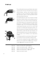
ProHead The modelling light is turned on and off with the black switch [1] at the back of the head. The built-in fan can easily be switched between continuous and thermostat-controlled operations [2]. Please note that when changing modelling light, flash tube or glass cover the lamp cable must be disconnected from the generator. The modelling light has a mini-can socket (E11). The flash tube has two metal pins. When removing a flash tube, pull it straight out of the sockets.
Pro-7b head ProHead Pro-7b head The Pro-7b head is a small and easily transportable flash head exclusively designed for the Pro-7b generator. Please note that when changing modelling light, flash tube or glass cover the lamp cable must be disconnected from the generator. The modelling light is a standard 100W lamp with an E11 socket. The flash tube has two pins. When removing a flash tube, pull it straight out of the sockets.
ProTwin The ProTwin is used to obtain extremely short flash duration, very quick recycling or to get 4800 Ws out of one single head. There are two flash tubes in a ProTwin. As the flash duration is shorter at low power settings, and as only half of the desired power is used in each tube, consequently shorter flash duration is obtained. For example if you need 1200 Ws, you fire 600 Ws from each tube, and your flash duration is shorter than if a standard ProHead is used.
ProTwin or glass cover the lamp cable must be disconnected from the generator. The modelling light has a mini-can socket (E11). The flash tube has two metal pins. When removing a flash tube, pull it straight out of the sockets. When inserting a new flash tube, check that the trigger-wire clasps properly around the flash Magic arm tube (please see mounting instructions in package). Fits ProHead, Pro-7b head When mounting the glass cover, check that both locking and ProTwin.
Pro-7 ring The ring flash fits all Pro-7 generators, and is an entirely mobile source of light. The interior diameter of 100 mm provides plenty of space for professional camera lenses. Since the camera holder can be tilted forward and backwards, as well as upwards and downwards, most cameras can be attached. This makes an excellent source of light in cramped areas, such as the interior of an automobile. Many fashion photographers also use the ring flash to find new angles and capture details.
Pro-7 Generators
Pro-7a 1200/2400 Generator Contents Nomenclature . . . . . . . . . . . . . . . . . . . . . .15 Brief Instructions . . . . . . . . . . . . . . . . . . . .16 Mains Connection . . . . . . . . . . . . . . . . . . . .16 Connecting Lamp Heads . . . . . . . . . . . . . . .16 Energy Distribution . . . . . . . . . . . . . . . . . .17 Energy Control . . . . . . . . . . . . . . . . . . . . . .18 Choice of Modelling Light . . . . . . . . . . . . . .18 Connecting Camera & Flash Meter . . . . . . . .19 Recharging . . .
1. Mains (AC) Connection 9. Sync Sockets 2. Lamp Head Sockets A, B1 & B2 10. Photocell Button On/Off 3. Indicator for Mains (AC) Connection 11. Ready Lamp & Test Button 4. Mains (AC) Power On/Off 12. Audible Signal On/Off 5. Energy Dial for Lamp Socket A 13. Slow/Fast Recharging Button 6. Energy & Bracketing Control 14. Turbo Recharging Button On/Off 7. Energy Dial for Lamp Sockets B1 & B2 15. Modelling Light Control 8. Photocell 16.
Pro-7a 1200/2400 Generator Brief Instructions Connect the generator to the mains supply with the enclosed power cable [1]. The green lamp [3] should now light up indicating acceptable AC current to the generator. • Connect the desired lamp heads to the sockets A, B1 & B2 [2]. • Use the control [15] marked MOD.LIGHT to choose modelling light mode. • Press the button [4] marked ON to start charging. The white ready lamp [11] will light up when the generator is fully charged. • Choose energy distribution.
[1] [2] [3] Pro-7a 1200/2400 Energy Distribution When only one lamp head is in use, choose the A socket. Only the A socket can be used to release the generator’s total energy to one lamp head. Use dial A to adjust energy in 1/3 f:stop increments from full (1/1) down to (1/8) energy, which is [6] equivalent to four [4] f:stops. PLEASE NOTE ! When the dial is positioned to release more than 1/2 energy (within the area marked A ONLY) always point the dial B towards the red indicator [16].
[4] [6] [9] PLEASE NOTE! The energy output is determined by the energy dials A and B. The energy output will remain consistent, regardless of which lamp sockets are used or the number of lamp heads connected to them. Energy dumping is not necessary as long as the dial MASTER is turned to MAX. Energy Control The generator’s total energy is regulated with the control MASTER (6). The total energy can be adjusted in 1/6 f:stop increments from MAX down to minus 8/6 f:stops equivalent to 1 1/3 f:stops.
[11] [13] [14] Pro-7a 1200/2400 Connecting Camera and Flash Meter The two sync sockets [9] allow the camera and flash meter to be connected simultaneously. The 5 meter sync cord can without restrictions be elongated with a sync extension cable. Connecting generators can be done by means of the Profoto sync [15] interconnection cord or by so called ”hard wiring”. Recharging The recharging starts when the push-button [4] is activated. Slow, fast or turbo recharge can be chosen.
[6] [8] [10] Photocell The built-in photocell [8] will sense flash release as well as IR-signals from most IR-transmitters. The photocell is disabled when the button [10] SLAVE is released. Bracketing Manual exposure variations are performed as follows: • Point the MASTER control [6] at the arrow and release an ”open” flash by pressing the test button [11]. • Set the lighting as you would normally do, determine the appropriate f:stop and shoot the first frame.
[11] [14] • The generator will now recharge for an overexposed frame, which is indicated by the ready Pro-7a 1200/2400 lamp lighting up for longer periods. • Shoot the second frame • The generator will now recharge for an underexposed frame, which is indicated by the ready lamp lighting up for shorter periods • Shoot the third frame • The generator will now recharge for a normal exposure, and so on. Turn the MASTER control towards the arrow each time new light readings are made.
[3] [5] [6] Signals, Visible & Audible The green indicator [3] below the handle will light up when the generator is connected to the mains supply. The white ready lamp button [11] will light up when the generator is fully charged. The characteristics of the light vary (please see ”Autobracketing” page 20). When the generator is fully charged a short ”beep” can be heard. Releasing the button [12] marked SOUND can turn off this signal.
[12] [11] [16] Pro-7a 1200/2400 Colour Temperature The Pro-7 generators are perfectly suited for critical analouge (film) and digital shoots. The colour temperature is constant and reliable regardless of the energy output chosen with the dials A, B1 & B2. The colour temperature can be adjusted with the MASTER control [6]. Each 1/6 increment reduces the colour temperature by 50° Kelvin, which means a total downscale of 400° Kelvin.
Technical Data Pro-7a/1200 Pro-7a/2400 Guide numbers in metres/feet at 100 ASA with a Magnum 50° Reflector Flash Duration (t 0.5) at: 4800 Ws 140/460 201/660 Pro-7 head Pro-7 twin Pro-7 head Pro-7 twin – – – 1/1600 sek 2400 Ws – 1/2200 sek 1/1600 sek 1/2200 1200 Ws 1/2200 sek.
Pro-7s 1200/2400 Generator Contents Nomenclature . . . . . . . . . . . . . . . . . . . . . . . . 26 Brief Instructions . . . . . . . . . . . . . . . . . . . . . . 27 Mains Connection . . . . . . . . . . . . . . . . . . . . . . 27 Connecting Lamp Heads . . . . . . . . . . . . . . . . . 28 Energy Control . . . . . . . . . . . . . . . . . . . . . . . . 28 Choice of Modelling Light . . . . . . . . . . . . . . . . 28 Connecting Camera & Flash Meter . . . . . . . . . . 29 Recharging . . . . . . . . . . . . . . .
Nomenclature Pro-7s Generator 1. Mains Connection 7. Sync Sockets 2. Lamp Head Sockets 8. Photocell Button On/Off 3. Indicator for Mains (AC) Connection 9. Ready Lamp & Test Button 4. Mains (AC) Power On/Off 10.Audible Signal On/Off 5. Energy Dial 11.Recharging Button Slow/Fast 6. Photo/IR-cell 12.
Pro-7s 1200/2400 Generator Brief Instructions • Connect the generator to the mains supply with the enclosed power cable [1]. The green lamp [3] should now light up indicating acceptable AC current to the generator. • Connect the lamp head(s) to the socket(s) [2]. • Use the control MOD. LIGHT [12] to choose modelling light mode. • Press the button [4] ON to start charging. The white ready lamp [9] flashes the first time the generator is charged indicating that ”dumping” of energy is needed.
[2] [4] [5] Connecting Lamp Heads One or two lamp heads can be connected to the lamps head sockets [2]. When connecting the lamp head plug, align the dots on the plug with the white dot on the generator panel. Secure by turning the locking ring on the plug clockwise. Energy Control The energy output is regulated with the control ENERGY [5]. The energy can be adjusted in 1/6 f:stop increments, from 1/1 down to 1/32 of the total energy (equivalent to six f:stops).
[9] [11] [12] Connecting Camera & Flash Meter The two sync sockets [7] allow the camera and flash meter to be connected simultaneously. The 5 M sync cord can be extended without limitations with sync extension cords. Further sync connections can be made with the Profoto sync interconnection cable or by so called ”hard wiring”. A slave signal from the photocell can be forwarded through this cable to another flash generator. Recharging The recharging starts when the ON/OFF button is pushed down.
[3] [6] [8] Photocell The built-in photocell [6] will sense flash release as well as IR-signals from most IR-transmitters. The photocell is disabled when the button marked SLAVE [8] is released. Signals, Audible & Visible The green indicator [3] below the handle will light up once the generator is connected to the mains outlet. The white ready lamp [9] will light up when the generator is fully charged. The button will not light up when the modelling light control [12] is in the OFF position.
[9] [10] [12] Reliability Testing - The R-Test The Profoto R-test guarantees that all products leaving the factory meet the very high standards required of professional equipment by professional photographers. The R-test is a rigorous performance test that the Profoto generators are put through - 720 full power flashes are released during one hour, which is equivalent to 20 rolls of 35 mm film.
Technical Data Pro-7s Pro-7s/1200 Pro-7s/2400 Guide numbers in metres/feet at 100 ASA with a Magnum 50° Reflector Flash Duration (t 0.5) at: 4800 Ws 2400 Ws 1200 Ws 600 Ws 300 Ws 150 Ws 75 Ws 37,5 Ws 18.75 Ws 140 Pro-7 head – – 1/2200 sec. 1/3200 1/4500 1/5300 1/8000 1/8000 1/12000 Pro-7 twin – 1/2200 sec. 1/3200 1/5300 1/6800 1/8000 1/12000 1/12000 – 201 Pro-7 head – 1/1600 sec. 1/2200 1/2700 1/3200 1/5300 1/5300 1/8000 – Pro-7 twin 1/1600 sec.
Pro-7b Generator Contents Nomenclature . . . . . . . . . . . . . . . . . . . . . . . . . . 34 Brief Instructions . . . . . . . . . . . . . . . . . . . . . . . 35 Battery and Battery Charging . . . . . . . . . . . . . . . 35 Changing Battery . . . . . . . . . . . . . . . . . . . . . . . 36 Connecting Lamp Heads . . . . . . . . . . . . . . . . . . 36 Energy Control . . . . . . . . . . . . . . . . . . . . . . . . . 36 Choice of Modelling Light . . . . . . . . . . . . . . . . . .
Nomenclature Pro-7b Generator 1. Lamp Head Sockets 8. Ready Lamp & Test Button 2. SYM/ASYM Switch 9. Audible Signal On/Off 3. Indicator for Battery Charge 10. Recharging Button Slow/Fast 4. Charge Outlets 11. Modelling Light Control 5. Photo/IR-cell 12. On/Off Switch 6. Sync Sockets 13. Energy Control 7.
Pro-7b Generator Brief Instructions • Connect the desired number of lamp heads to sockets A & B. • Start charging by pushing the button ON [12]. The ready lamp [8] will light up when the generator is fully charged. • The generator can be activated from OFF position by means of a sync signal from a camera. • Choose the desired energy distribution with the control MASTER [13] and the SYM/ASYM switch [2]. The generator will automatically dump if the energy level is lowered.
[1] [2] Changing Battery By putting the two handles at the bottom together the battery cassette is released and the battery can easily be pulled out. A new battery is pushed all the way into the generator and is locked by directing the handles away from each other. When changing the battery it must be mounted in a battery cassette by an authorised service station. If the battery is not purchased at Profoto a Hitachi HV 12 -12 unit must be used.
[8] [11] [13] head is connected to B half the energy is obtained if the SYM/ASYM switch is in position A 1/1 (1/2), B 1/2. If the switch is in the position A 1/2, B 1/4 a quarter of the chosen energy is obtained. Two lamp heads: The energy chosen with the MASTER [13] control can either be distributed evenly through the two lamp heads (the SYM/ASYM switch in the position A1/1 (1/2), B 1/2) or twice as much energy (equivalent to one f:stop) through A as B (the SYM/ASYM switch in the position A 1/2, B 1/4).
[3] [5] [7] Recharging The recharging starts when the ON/OFF switch [12] is pushed down. Slow or fast recharging can be chosen. When the button FAST [10] is released, the generator will recharge slowly. Push the FAST button [10] for normal recharging cycles; this is sufficient for most kinds of photography. The recharging time is approx. 2.8 sec at full energy. When extremely short recharging times are required, for instance when operating a motor-drive camera, choose lower energy settings.
[8] [9] [10] Safety Functions If the generator for any reason whatsoever overheats, the recharging will completely stop. After a while, when the temperature has gone down sufficiently, the generator will start recharging at a normal pace again. No recharging can [11] take place when the red light of the battery indicator is on. This is a safety feature protecting the battery from harmfully low discharging. There are three fuses on the battery cassette.
[13] Colour Temperature The Pro-7 generators are perfectly suited for critical analouge (film) and digital shoots. The colour temperature is constant with a variation of a maximum of +/- 150° Kelvin. PLEASE NOTE: combining flash tubes and/or glass covers with different coatings can make even more distinctive colour temperature adjustments. Flash Duration Reducing the energy output with the control MASTER [13] shortens the flash duration. The shortest flash duration using a Pro-7 head is 1/3000 sec.
Technical Data Pro-7b Battery 250 flashes at full energy per battery charge (180 flashes at the fastest recharging) Guide numbers in metres/feet at 100 ASA with Magnum 50° Reflector 140/460 Flash Duration (t 0.5) at: Pro-7 head or Pro-7 twin Pro-7b head 2400 Ws – 1/1400 sec. 1200 Ws 1/1400 sec.
Product codes, descriptions and included components may vary from market to market around the world. Please consult your local dealer or distributor for specific information. 34 40 71/ Photos: Jan Fridlund. Chart an top panels by: Gert Jansson. Profoto AB Box 2023, SE 128 21 Skarpnäck, Sweden. Phone +46 (0)8-447 53 00, Fax +46 (0)8-447 53 20. Email info@profoto.se www.profoto.