
Integration Manual


RMI3
9
www.profoto.com
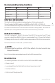
Recommended Operating Conditions
Parameter Min Max Unit
DC Supply 2.7 3.5 V
Current 0.18 A
Temperature -10 +55 °C
Humidity 0 90 % rel n.c
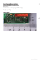
Interface Description
The interface to the host system is implemented as a 16 pin male connector.
The part used on the RMI3 module is an AMP Micro-MaTch (P/N: 8-215464-6).
The recommended matching female connector is P/N: 8-215079-6. It is recommended
to connect the module with a female header mounted in through holes. This allows for
optimum space saving and leaves the antenna connector easily accessible.
UART Serial Interface
The UART is using pins 1, 8 and 15. To connect to an RS232 line you must use a TTL level
converter (a dongle from B&B Electronics is recommended) from 3.3V or use the Profoto Air
USB dongle which mates with an RMI3 module and provides a USB interface to a computer.
Serial characteristics: 38400. 8, N, 1 (no flow control)
NOTE!
Connecting the module to an RS232 line without a line level converter may
damage the module.
For a list of available commands please refer to the RUF documentation.
Reset Interface
The following conditions will lead to a reset on the Promote RMI3 module:
• Power on reset
• Low voltage (Brown Out) detected from internal supervisory circuit
• Reset by Software
• External reset through reset pin