
Installation Guide


****************************************************************************************************************************************************************************************************
(06/18/14) REV. D
P87-AT
Follow this instruction sheet carefully. Be sure electricity is OFF before starting installation.
SPEC.NO. 023856
Assembly & Installation Instructions
Read instructions carefully and turn electricity off at main
circuit breaker panel before beginning installation.
CAUTION:
PAGE 1 of 4
WARNING: When using Special Control Devices with this fixture, follow instructions carefully to assure NEC
compliance. For more help, contact a Qualified Electrical Contractor.
WARNING: This product contains chemicals known to the State of California to cause cancer, birth defects
and/or other reproductive harm. Thoroughly wash hands after installing, handling, cleaning, or otherwise touching
this product.
CAUTION: To complete the installation, choose only UL Listed Progress Trims from the label inside the Housing.
The use of any trim not listed in this Fixture is a Violation of NEC Article 110-3 (B) and Voids All Warranties.
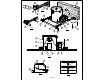
1. For I.C. APPLICATIONS where the Fixture may be in direct Contact with the insulation, remove the Peel-Off
Warning Label (1) from the Housing (3) that reads: "WARNING RISK OF FIRE, DO NOT INSTALL INSULATION
WITHIN 3 INCHES OF THE SIDES OF THE HOUSING".
2. FOR NON-I.C. APPLICATIONS where, except for mounting points, the Fixture is installed at least 1/2 inch
from any combustible surface and Insulation is a minimum of 3 Inches from all sides, Remove Peel-Off I.C.
Wattage Label (2) from inside the Housing (3).
3. For Wooden Joists: Use the Centering Notches (4) located on the Plaster Frame to position the Fixture. Extend
the Bar Hangers (6), use joist alignment tabs to locate fixture and hammer the 4 Nails (7) into Joists (8). Drive
additional nails through holes in Bar Hanger for alternate support if required. Bars may be shortened at score
mark to fit tight mounting conditions and joist alignment tabs removed to adjust vertically as needed by breaking
off with pliers.
4. On Suspended Ceilings: Place the Fixture on the ceiling grid with the "T" Bars (9) running through the Bar
Hanger Notches (10). Using a flat head screwdriver or other tool, bend the integral t-bar mounting tabs (11)
downward to a vertical position (Fig. 3). Secure housing to the support structure with tie wire (supplied by others)
in the holes supplied. Sheetmetal screws (supplied by others) can also be used in the holes supplied (20).
5. Locate Housing along Bar Hanger in desired position and, using pliers, squeeze the 4 Locking Tabs (12) on
the Plaster Frame (13) tightly over the Bar Hangers to prevent further Housing movement. Bar Hangers (6) may
be installed in alternate Slots (23) if mounting conditions require.
6. Unsnap Junction Box Cover (14) by lifting the Leaf Spring.
7. Run supply wires through UL Listed connectors (not supplied) in one of the five Pryouts (15) on the Junction
Box (16) or Type NM cable (ROMEX) through an Opening above the Wire Retaining Plate (17). Connect Supply
Wires (19) as shown in Fig 4 & 5. Replace Cover.
8. FOR AIR-TIGHT APPLICATIONS, such as Washington State Energy Code Requirements, the Progress
housing is compliant with ASTME283 restricted air flow regulations. Always follow local building codes to ensure
compliance.
9. Loosen Screws (21) to adjust Housing (3) for variations in ceiling thickness. Bottom of Housing should be flush
with ceiling (22) within tolerance. Slot Covers (18) can be rotated 180 degrees in thick ceiling applications to
maintain Air-Tight requirements, "V" should be facing outward.
10. Select a Trim from the Wattage Label inside the Housing. Use Only Lamp Types approved for the Trim
chosen. DO NOT EXCEED MAXIMUM LISTED WATTAGE(S)! Follow instructions with Trim to complete
installation.
(Ceiling Opening is to be 6-7/8" Dia.)
Remove Socket Paint Cap prior to installing Trim and Lamp