ITEM #1233226 #1233227 #1233228 #1328816 BATHROOM FAUCET MODEL #F51B0066OB #F51B0066CP #F51B0066NP #F51B0066YP PROJECT SOURCE and PROJECT SOURCE & Design are trademarks or registered trademarks of LF, LLC. All rights reserved. Español p. 11 ATTACH YOUR RECEIPT HERE Serial Number Purchase Date Questions, problems, missing parts? Before returning to your retailer, call our customer service department at 1-866-389-8827, 8 a.m. - 8 p.m., EST, Monday - Friday.
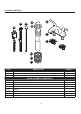
PACKAGE CONTENTS GG HH FF A EE DD B C AA BB CC PART A B C AA BB CC DD EE FF GG HH DESCRIPTION Faucet Aerator (Preassembled to Faucet (A)) Lock Nuts DRAIN ASSEMBLY COMPONENTS Rubber Washer Large Rubber Washer Lock Nut Drain Body Plunger Lift Rod Lift Rod Strap Ball Rod 2 QUANTITY 1 1 2 1 1 1 1 1 1 1 1
SAFETY INFORMATION • Follow these installation instructions carefully. Proper installation is the installer’s responsibility. • Failure to follow correct installation procedures can cause the faucet to become loose, which can result in serious injury. • The product should be installed by a locally licensed plumber. NOTE: Please DO NOT use plumber’s putty on plastic components. Use silicone caulk if sealant is required. PREPARATION Before beginning assembly of product, make sure all parts are present.
ASSEMBLY INSTRUCTIONS 1. Turn off water supply. Remove existing faucet if necessary. 1 2. Place a bead of clear silicone sealant (not included) around the base of the faucet (A). Install faucet (A) through top of sink (not included). 2 A 3. 3 Tighten lock nuts (C) onto the faucet (A).
ASSEMBLY INSTRUCTIONS 4. 4 Determine which type of connection you will be making. (1) Ball nose risers (3/8” O.D. copper tubing) with coupling nuts (not included) or (2) 1/2” I.P.S faucet connectors. Attach water supply lines (not included) to the faucet (A). A 1 5. 2 5 Install drain body (DD) and rubber washer (AA) through top of sink (not included). Secure with large rubber washer (BB) and lock nut (CC). Note: Opening for ball rod (HH) must face towards rear of sink. AA DD 1 BB No 6.
ASSEMBLY INSTRUCTIONS 7. 7 Insert ball rod (HH) into drain assembly (DD). Tighten sleeve. HH 1 DD 2 8. 8 Insert lift rod (FF) through faucet (A). From underneath the sink, connect the lift rod (FF) to the lift rod strap (GG) by pushing the button and inserting the lift rod (FF) all the way into the seated space of the lift rod strap (GG). Release the button to lock. Pull lift rod (FF) and lift rod strap (GG) in opposite directions to ensure the lift rod is completely secure. FF FF 2 1 GG A 9.
ASSEMBLY INSTRUCTIONS 10 11 A B 10. Turn on water supply. 11. Remove aerator (B) from faucet (A). 13 12 B 13. Replace aerator (B). 12. Turn on both hot and cold water to flush out any debris and check for leaks around drain.
CARE AND MAINTENANCE • Clean periodically with a soft cloth. Avoid abrasive cleaners, steel wool and harsh chemicals as these will dull the finish and void your warranty. TROUBLESHOOTING PROBLEM POSSIBLE CAUSE CORRECTIVE ACTION Leak from under handle. Retainer nut has come loose. O-ring on cartridge is dirty or damaged. Tighten the retainer nut. Clean or replace O-ring. Aerator leaks or has an inconsistent water flow pattern. Aerator is dirty or misfitted.
REPLACEMENT PARTS LIST For replacement parts, call our customer service department at 1-866-389-8827, 8 a.m. - 8 p.m., EST, Monday - Friday. PART 1.1 1.2 DESCRIPTION PART # Metal Handle – Cold A079171C Metal Handle – Hot A079171H 2 Index Button 3 Handle Adapter A603A12 A517156 4 Retainer Nut A66D639 5.1 Ceramic Disc Cartridge - Cold A507180N 5.2 Ceramic Disc Cartridge - Hot A507179N 6 Putty Plate A011083 7 Lock Nut Set A504023 1.1 1.2 2.
ARTÍCULO #1233226 #1233227 #1233228 #1328816 GRIFO PARA BAÑO MODELO #F51B0066OB #F51B0066CP #F51B0066NP #F51B0066YP PROJECT SOURCE y PROJECT SOURCE & Design son marcas o marcas registradas de LF, LLC. Todos los derechos reservados. ADJUNTE SU RECIBO AQUÍ Número de serie Fecha de compra ¿Preguntas, problemas, piezas faltantes? Antes de volver a la tienda, llame a nuestro Departamento de Servicio al Cliente al 1-866-389-8827, de lunes a viernes de 8 a.m. a 8 p.m., hora estándar del Este.
CONTENIDO DEL PAQUETE GG HH FF A EE DD B C AA BB CC PIEZA DESCRIPCIÓN A Grifo B Aireador (Preensamblada al cuerpo del grifo (A)) C Contratuercas COMPONENTES DEL ENSAMBLE DEL DESAGÜE AA Arandela de goma BB Arandela de caucho grande CC Contratuerca DD Cuerpo del desagüe EE Tapón del desagüe FF Varilla de levantamiento GG SBarra de la varilla de elevación HH Varilla de bola 12 CANTIDAD 1 1 2 1 1 1 1 1 1 1 1
INFORMACIÓN DE SEGURIDAD • Siga con atención las siguientes instrucciones de instalación. El instalador tiene la responsabilidad de realizar una instalación adecuada. • Si no sigue los procedimientos correctos de instalación, el grifo puede soltarse y causar lesiones graves. • Un plomero certificado debe instalar este producto. NOTA: No utilice masilla de plomero en componentes plásticos. Si es necesario aplicar sellador, utilice masilla de calafateo de silicona.
INSTRUCCIONES DE ENSAMBLAJE 1. Interrumpa el suministro de agua. Si es necesario, retire el grifo existente. 1 2. Coloque un cordón de sellador de silicona transparente (no se incluye) alrededor de la base del grifo (A). Instale el grifo (A) a través de la parte superior del lavabo (no se incluye). 2 A 3. 3 Apriete las contratuercas (C) en el grifo (A).
INSTRUCCIONES DE ENSAMBLAJE 4. Determine qué tipo de conexión realizará. (1) Elevadores de punta esférica (tubería de cobre de 3/8 pulg de diámetro exterior) con tuercas de acoplamiento (no se incluyen) o (2) conectores para grifo IPS de 1/2 pulg. Conecte las tuberías de suministro de agua (no se incluyen) al grifo (A). 4 A 1 5. Instale el cuerpo del desagüe (DD) y la arandela de goma (AA) a través de la parte superior del lavabo (no se incluye).
INSTRUCCIONES DE ENSAMBLAJE 7. 7 Inserte la varilla de rótula (HH) en el conjunto de desagüe (DD). Apriete el manguito. HH 1 DD 2 8. 9. Inserte la varilla de levantamiento (FF) en el grifo (A). Desde debajo del lavabo, conecte la varilla de levantamiento (FF) a la correa para la varilla de levantamiento (GG), para esto presione el botón y pase la varilla de levantamiento (FF) por completo hasta el espacio asentado de la correa para la varilla de levantamiento (GG). Suelte el botón para asegu rarlo.
INSTRUCCIONES DE ENSAMBLAJE 10 11 A B 10. Restablezca el suministro de agua. 11. Retire el aireador (B) del grifo (A). 13 12 B 12. Abra las manijas de agua caliente y fría, deje correr el agua para eliminar cualquier desecho y revise si hay fugas alrededor del desagüe. 13. Vuelva a colocar el aireador (B).
CUIDADO Y MANTENIMIENTO • Limpie periódicamente con un paño suave. Evite utilizar limpiadores abrasivos, lana de acero y químicos agresivos, ya que pueden dañar el acabado y anular la garantía. SOLUCIÓN DE PROBLEMAS PROBLEMA Hay una fuga debajo de la manija. El aireador tiene fugas o el flujo de agua es irregular. CAUSA POSIBLE La tuerca de retención está floja. El aro tórico en el cartucho está sucio o dañado. El aireador está suelto o mal instalado. El aireador está suelto o no está instalado el sello.
LISTA DE PIEZAS DE REPUESTO Para obtener piezas de repuesto, llame a nuestro Departamento de Servicio al Cliente al 1-866-389-8827, de lunes a viernes de 8 a.m. a 8 p.m., hora estándar del Este. PIEZA 1.1 1.2 2 3 4 5.1 5.