INTELLI-WAVE 2000W PURE SINE WAVE INVERTER P/No.
IMPORTANT SAFETY INFORMATION Please read this manual thoroughly before use and store in a safe place for future reference. WARNINGS • For indoor use out of weather only. • For use with negatively earthed vehicles & systems only. • Internally bonded for safety, battery DC negative to case & AC socket earth. • Hazardous voltage inside – do not attempt to open, repair or use if damaged. • Only connect 230/240V AC appliances that are in safe condition.
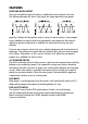
FEATURES PURE SINE WAVE OUTPUT There are two different types of inverters, modified sine wave and pure sine wave. The difference between the two is how closely the output replicates mains power. Logically it follows that the process used in a pure sine wave inverter is more complex than a modified sine wave inverter and subsequently more expensive. Most electric appliances operate unaffected on a modified sine wave and hence they are more common.
REMOTE CONTROL DISPLAY Control and monitor the inverter’s performance from a remote control display allowing the inverter to be mounted flush or surface mounted out of sight. Ideal for use in caravans, motor homes and boats. BI-COLOUR L.E.D DISPLAY THERMOSTATICALLY CONTROLLED 3 SPEED COOLING FAN • • • • • PROTECTION Low input voltage High input voltage Low battery alarm Over temperature Overload SPECIFICATIONS P/No.
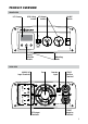
PRODUCT OVERVIEW FRONT VIEW LCD Screen RCD Safety Switch AC Output Sockets On/Off Switch 2000W Pure Sine Wave OFF ON OFF TEST VOLTS WATTS LOAD% ECO ON SAFETY SWITCH 2000W Pure Sine Wave OFF ON Display Selection Buttons VOLTS WATTS LOAD% ECO OFF Mounting Holes TEST ON SAFETY SWITCH REAR VIEW INPUT 240V a.c 50Hz input – Max connected output load 240V= a.c 2000W 50Hz input – Max connected output load = 2000W Wiring to be carried out by licensed electrician.
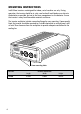
MOUNTING INSTRUCTIONS Intelli-Wave inverters are designed for indoor, out of weather use only. During operation, the inverter should be in a dry, cool and well-ventilated area as close to the batteries as possible, but not in the same compartment as the batteries. Ensure the inverter is away from flammable materials and fumes. The inverter end plates include a mounting flange for easy mounting.
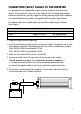
CONNECTING THE DC CABLES TO THE INVERTER It is important to use suitable cable lengths and sizes to get the most out of your inverter. Use of cable that is too thin or too long will result in voltage drop between the battery and inverter, and may trigger low voltage warnings and inverter shutdowns. It is recommended to place cable in corrugated conduit to protect from damage. The following table lists suitable cable sizes for different cable lengths available from Projecta.
CONNECTING THE AC CABLES TO THE INVERTER Note: Ensure a licensed Electrician wires the 240V AC mains and output terminals to and from the inverter. If the inverter is being installed in to a caravan/camper van ensure the unit & wiring is installed to AS3001. WIRING AC POWER FROM THE INVERTER AC output power can be wired directly from the OUTPUT terminals of the inverter allowing connection to external GPO’s in addition to the outputs located on the front of the IP2000 unit. 1.
WIRING AC MAINS POWER TO THE INVERTER 1. Ensure the inverter is turned off and disconnected from DC power, also ensure AC mains wiring to be connected to the inverter is isolated and safe to work with. 2. To gain access to the INPUT terminals remove the cover located at the back of the unit using a phillips head screw driver. 3. Select suitable size cable glands/conduit fittings (16mm or 20mm) & cable to be wired to the INPUT terminals. Ensure multi strand cable is used as per AS3001.
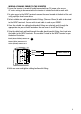
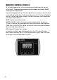
REMOTE CONTROL DISPLAY To install the remote control, insert the data plug into the data socket at the rear of the inverter. To operate the inverter using the remote, the inverter On/Off switch must be turned to ON. The remote is equipped with an LCD screen identical to the inverter, as well a bi-colour status L.E.D and audible alarm. During normal operation, the LCD screen will default to the VOLTS display (input battery voltage).
MOUNTING REMOTE CONTROL FLUSH MOUNT • Cut a 93mm x 70mm hole into the desired mounting surface to suit the supplied mounting plate. • Position the mounting plate into the hole with the side labelled ‘FLUSH MOUNT’ facing outwards and screw the supplied screws into the mounting surface as per the below illustration. FLU OU SH M NT • Clip the remote control into the mounting plate.
REMOVING REMOTE CONTROL S STATU FLUSH MOUNT 1. Pull the remote control sideways and firmly lift 2. The remote will click out of place VOLTS /ON OFF ECO LTS TS/ WATAD% LO VO S STATU S STATU N N OFF / TTS WA AD% LO LTS S/ WATT % LOAD ECO / TTS WA AD% LO STAT US VO N VOLTS /ON OFF S/ WATT % LOAD ECO OFF/O ECO TS/ WATAD% LO TS SURFACE MOUNT 1. Holding the remote on either side, push upwards. 2. Squeeze the sides together to lift away.
UNDERSTANDING YOUR INVERTER These inverters are equipped with an audible alarm and a multi-function LCD screen with selection buttons allowing you to monitor the inverter’s performance. During normal operation, the LCD screen will default to the VOLTS display (input battery voltage).
OPERATING INSTRUCTIONS To operate the inverter turn the inverters On/Off switch to ON. The inverter will beep momentarily while it carries out a brief self-analysis before supplying power to the AC socket. To turn off, turn the inverter On/Off switch to OFF. Note: Ensure the RCD Switch is down, the red indicator will be showing. Note: Where possible the inverter will automatically select 240V AC mains power rather than DC battery power during operation. To help prevent the inverter being overloaded: 1.
FAULTS & ERRORS Problem Possible Cause Solution Low battery voltage Input battery voltage is below 10.5V (12V), 21V (24V) a) Recharge battery b) Battery may be too small. Refer to pg 16 for recommended battery sizes c) Check cable connections and that cable sizes are sufficient (see pg 6) Low battery Shutdown a) The input battery voltage is below 10V (12V), 19.5V (24V) a) Recharge battery immediately.
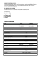
UNDERSTANDING YOUR POWER REQUIREMENTS POWER REQUIREMENTS OF YOUR APPLIANCE/S: All appliances have a rating plate that shows the amount of power (Watts) used or the current (Amps) drawn under normal use. The following table shows the maximum combined AC Watts or AC Amps which can be run by the inverter. P/No. IP2000 AC Combined maximum load (Watts) 2000W AC Combined maximum load (Amps) 8.
TROUBLESHOOTING/FAQ: Q. Why does the inverter turn itself off? A. If the inverter’s audible alarm sounds and a fault L.E.D illuminates, this indicates that there is a fault or error, and the inverter may turn off. Most commonly this would be caused by an appliance that is drawing too much power (overloading), low battery voltage or voltage drop due to insufficient size cables or poor connections (refer to ‘Faults & Errors’ table, page 15). Q.
Q. Why does it damage the inverter if the battery leads are reverse-connected? A. Your inverter uses sophisticated electronics to convert DC battery power to AC mains power. If you accidentally connect the inverter to the battery incorrectly (reverse polarity) a large current will be drawn by the inverter which will blow the protection fuse. As this occurs some of the high current could damage sensitive electronic components.