
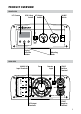
Manual
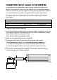


CONNECTING THE DC CABLES TO THE INVERTER
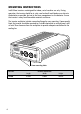
It is important to use suitable cable lengths and sizes to get the most out of your
inverter. Use of cable that is too thin or too long will result in voltage drop between
the battery and inverter, and may trigger low voltage warnings and inverter shutdowns.
It is recommended to place cable in corrugated conduit to protect from damage.
The following table lists suitable cable sizes for different cable lengths available
from Projecta.
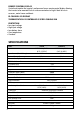
Cable Specifications
Cable Length 0–3m 3–6m
IP2000 IWK6 (3m, 49mm
2
) Not Recommended
IP2000-24 IWK3 (3m, 32mm
2
) IWK5 (6m, 64mm
2
)
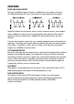
1. Prepare all cable ends with cable lugs.
2. Install a circuit breaker or high current fuse and fuse holder in the positive line as close
to the battery as possible. The following fuse & fuse holder is available from Projecta
P/No. IFB-250 (250A fuse and holder) 12 Volt
P/No. IFB-150 (150A fuse and holder) 24 Volt
3. Make sure the inverter On/Off switch is turned OFF.
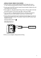
4. Connect the cables to the DC input terminals on the rear of the inverter.
The red terminal is positive (+) and the black terminal is negative (-).
a. Connect the positive cable to the inverter and battery positive terminals.
b. Connect the negative cable to the inverter and battery negative terminals.
5. The inverter is earthed through the negative DC input cable. Additional earthing
can be wired from the DC negative terminal.
7
FUSE
CORRUGATED CONDUIT