INTELLI-RV 12V POWER MANAGEMENT SYSTEM P/No.
IMPORTANT SAFETY INFORMATION Please read this manual thoroughly before use and store in a safe place for future reference. WARNINGS ß ([SORVLYH JDVHV 3UHYHQW öDPHV DQG VSDUNV 3URYLGH DGHTXDWH YHQWLODWLRQ GXULQJ FKDUJLQJ • Before charging, read the instructions • For indoor use. Do not expose to rain ß )RU FKDUJLQJ OHDG DFLG EDWWHULHV 21/< RI WKH VL]H YROWDJH VSHFLõHG LQ WKH VSHFLõFDWLRQV WDEOH • Always charge the battery on the correct voltage setting.
CONTENTS 1. INTRODUCTION .....................................................................................................................4 1.1 1.2 1.3 1.4 Features Monitor 10 Position Switch panel Bedroom Switch panel :DWHU WDQN SUREH 5 6 6 7 2. KEY FEATURES AND FUNCTIONS ..........................................................................................8 2.1 2.2 2.3 2.4 2.5 2.7 2.8 2.9 2.10 2.
1. INTRODUCTION 30 LV GHVLJQHG IRU FDUDYDQ RU PRWRU KRPH ZLWK LQWHJUDWLQJ PDQ\ IXQFWLRQV LQFOXGLQJ EDWWHU\ FKDUJHU GLVWULEXWLRQ EORFNV 0337 VRODU FKDUJHU FRQWUROOHU FKDUJLQJ UHOD\ ORZ YROWDJH GLVFRQQHFW ZDWHU SXPS FRQWUROOHU ZDWHU WDQN LQGLFDWRU SUHFRQõJXUHG VZLWFK SDQHOV as well as a crystal central monitor. The PM400 is designed for an easy installation and user-friendly interface.
1.
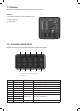
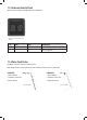
1.2 Monitor The monitor is a digital control center for complete on-board power system. Features: ß 7 %XV GHVLJQ FDQ EH FRQQHFWHG WR PXOWLSOH GHYLFHV • System monitoring ß &RQõJXUDWLRQ Figure 3 Overview of Monitor 1.3 10-Position Switch Panel 30 6: VZLWFKHG SDQHO ZDV SUHFRQõJXUHG ZLWK IXQFWLRQV OLVWHG DV EHORZ 7DEOH 1 2 3 4 5 6 7 8 9 10 Figure 4 Overview of 10 Position Switch Panel PM4SW10 No.
1.4 Bedroom Switch Panel With two bedroom switches, the PM400 offers extra customisation. Figure 5 An overview of Switch Panel PM4SW2 No. 1 2 NAME Bedroom light Night light TYPE DC load control Scene mode DESCRIPTION Load control, support brightness adjustment Load control, support brightness adjustment. Refer to Chapter 2.11 Table 2 Function list of PM4SW2 1.5 Water Tank Probe For PM400, a maximum of 4 probes can be monitored.
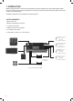
2. KEY FEATURES AND FUNCTIONS 2.1 Multiple Inputs 7KH 30 DFFHSWV LQSXWV IURP $& PDLQV 6RODU DQG 6WDUWHU %DWWHU\ $OWHUQDWRU +RZHYHU only one source will provide power at one time, see table below for details:- x x AC MAINS SOLAR x x x x STARTER BATTERY DOMINATING SOURCE AC MAINS AC MAINS STARTER BATTERY Table 3 Input Priority 2.
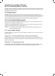
2.3 Vehicle Battery Charger $ORQJ ZLWK D SRZHUIXO FKDUJHU IRU VHUYLFH EDWWHU\ 30 RIIHUV D öRDW FKDUJH RI XS WR $ WR NHHS WKH VWDUWHU EDWWHU\ FKDUJHG ZKHWKHU connected to the AC main or PV. When the starter battery is less than 12.4V, the PM400 starts charging after 30 minutes delay and stops charging when voltage reaches 12.8V. 2.4 Power Supply Mode ,I QR EDWWHU\ LV DWWDFKHG WR 30 XQLW LW ZLOO ZRUN DV D SRZHU VXSSO\ DXWRPDWLFDOO\ ZLWK D 9'& RXWSXW 2.
2.8 Battery Low Voltage Protection (BLVP or commonly known as an LVD) The PM400 unit has a built-in battery low voltage protection relay. It will disconnect the load once the battery voltage drops below the threshold voltage. The default setting is 10.5Vdc and it can be changed by crystal central monitor or mobile APP from 10.0Vdc to 11.7Vdc. 2.9 Battery Switch The PM400 unit offers a convenient way to switch off the output of the service battery on-board.
3. STRUCTURE AND INSTALLATION 3.1 PM400 Power Management System 3 4 5 1 2 6 7 26 8 Figure 10 Front panel of PM435 9 25 10 11 12 13 14 15 16 17 18 No.
Figure 11 Dimension of PM435 (Unit: mm) Installation PM435 can be installed on a horizontal surface or vertically on a wall. Please see following instructions: Ensure clearance on both sides of PM435 unit upon installation. A recommended clearance of 5cm on each side. 3.
3.3 10 and 2 Position Switch Panel Figure 15 Dimension of PM4SW10 (Unit: mm) Figure 16 Dimension of PM4SW2 (Unit: mm) Installation Figure 17 Installation of PM4SW10 (Unit: mm) Figure 18 Installation of PM4SW2 (Unit: mm) 3.4 Water Tank Probe 3.4.1 PMWS400 Water Tank Probe Figure 19 Dimension of PMWS400 (Unit: mm) 3.4.
4. WIRING 4.1 Material 4.
8 PM4SW2 2 Pos.
5. DISPLAY 5.1 PM400 Power Management System 1 2 3 4 5 P/No. PM335 Figure 27 An overview of PM435 No.
5.2 10 Position Switch Panel PM4SW10 1 6 2 3 7 4 8 9 Figure 28 An overview of PM4SW10 5 10 No. 1 2 3 4 5 6 7 8 9 10 NAME Ceiling light Bedroom light Dinning light Outside light Night mode Water pump TV Switch A Switch B Load TYPE DESCRIPTION DC load control Load control, support brightness adjustment Scene mode Load control, on/off control Refer to Chapter 2.11 DC load control Load control, on/off control Refer to Chapter 1.3 Table 10 Button explanation of PM4SW10 5.2.
5.3.1 Monitor Symbol Explanation No.
5.3.3 Alphabet Explanation CHARACTER ALPHABET A B C D E F G + I J K L M N O P Q R S T U V X Y Table 15 Alphabet explanation 6. OPERATION ,I WKHUH LV FRQöLFW EHWZHHQ WKH FRQõJXUDWLRQ RQ 30 DQG WKH PRQLWRU WKH PRQLWRU ZLOO öDVK DV D UHPLQGHU &RQõJXUDWLRQ RQ 30 ,I WKHUH LV FRQöLFW EHWZHHQ WKH FRQõJXUDWLRQ RQ 30 DQG WKH PRQLWRU WKH PRQLWRU ZLOO öDVK DV D UHPLQGHU 6.1.
6.1.
0RQLWRU &RQõJXUDWLRQ 0HQX Figure 36 Main menu of setting Figure 37 Date and Time setting Figure 38 Battery Type setting Figure 39 Battery Capacity setting Figure 40 Low Voltage Protection setting Figure 41 Water Pump Enable/Disable setting Figure 42 Restore factory setting )LJXUH 8SGDWH õUPZDUH 6.3 Operation of Switch Panels PM4SW10 and PM4SW2 6.3.1 Dimming Operation There are three buttons on the PM4SW10 which can support brightness adjustment.
6.4 MAINTENANCE 6.4.1 Battery Monitor Maintenance There is a built-in battery measurement in the PM400 system. To assure the accuracy, maintain the system with the following instructions: )XOO\ FKDUJH WKH EDWWHU\ IURP $& JULG LQVWHDG RI 39 HYHU\ ZHHNV 2. Do a full charge to the battery every 3 months. ß &KDUJH WKH EDWWHU\ ZLWK $& JULG XQWLO WKH ×&+*Ø /(' OLJKW RQ 30 unit or ‘FLOAT’ shows on the monitor 6.4.
8. SPECIFICATION MODEL ELECTRICAL SPECIFICATIONS Grid Nominal input voltage 9 Power factor Input current at full load Battery Starter Battery Starter battery voltage range Service battery Service battery voltage range PV Charger type Open circuit voltage Max supply current Max charging current Charging 5HOD\ VSHFLõFDWLRQ Relay PM435 240±10%VAC +] 0.95 2.5A MODEL ELECTRICAL SPECIFICATIONS Battery Disconnect voltage Disconnect /9' Delay off time Reconnect voltage 12VDC 12.